Installation
March 2006
2-7
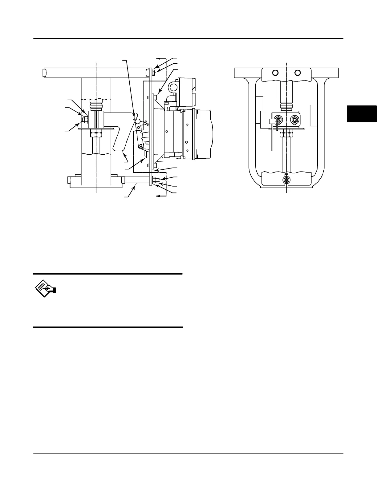
Figure 2-4. Type DVC6020f Digital Valve Controller Mounted on Long-Stroke Sliding-Stem Actuator.
PLAIN WASHER
HEX NUT
STUD, CONT
THREAD
A
LOCK WASHER
CAP SCREW
MOUNTING PLATE
CAP SCREW, HEX SOCKET
VENT
PLAIN WASHER
HEX NUT
STUD, CONT THREAD
A
SPACER
SECTION A-A
CAM
CAM/ROLLER POSITION MARK
29B1665-A / DOC
controller on the actuator. See the instructions that
come with the mounting kit for detailed information on
mounting the digital valve controller to a specific
actuator model.
Note
All cams supplied with FIELDVUE
mounting kits are characterized to
provide a linear response.
Type DVC6020f digital valve controllers use a cam
(designed for linear response) and roller as the
feedback mechanism. Figure 2-4 shows an example of
mounting on sliding-stem actuators with travels from 4
inches to 24 inches. Some long-stroke applications will
require an actuator with a tapped lower yoke boss.
Figures 2-5 and 2-7 show the Type DVC6020f
mounted on rotary actuators.
As shown in figure 2-5, two feedback arms are
available for the digital valve controller. Most
long-stroke sliding-stem and rotary actuator
installations use the long feedback arm [62 mm (2.45
inches) from roller to pivot point]. Installations on
Fisher Type 1051 size 33 and Type 1052 size 20 and
33 actuators use the short feedback arm [54 mm (2.13
inches) from roller to pivot point]. Verify that the
correct feedback arm is installed on the digital valve
controller before beginning the mounting procedure.
Refer to figures 2-4, 2-5, and 2-7 for parts locations.
Refer to the following guidelines when mounting on
sliding-stem actuators with 4 to 24 inches of travel or
on rotary actuators:
1. Isolate the control valve from the process line
pressur and release pressure from both sides of the
valve body. Shut off all pressure lines to the
pneumatic actuator, releasing all pressure from the
actuator. Use lock-out procedures to be sure that the
above measures stay in effect while working on the
equipment.
2. If a cam is not already installed on the actuator,
install the cam as described in the instructions
included with the mounting kit. For sliding-stem
actuators, the cam is installed on the stem connector.
3. If a mounting plate is required, fasten the mounting
plate to the actuator.
4. For applications that require remote venting, a
pipe-away bracket kit is available. Follow the
instructions included with the kit to replace the existing
mounting bracket on the digital valve controller with
the pipe-away bracket and to transfer the feedback
parts from the existing mounting bracket to the
pipe-away bracket.
5. Larger size actuators may require a follower arm
extension, as shown in figure 2-7. If required, the
2
 Loading...


