S600 Instruction Manual
3.4 CPU On-Board Connectors
Table 3-8 shows the miscellaneous device connectors provided on the
P152 CPU module. This information is for identification purposes
only. Do not modify these connections unless told to do so by the
factory.
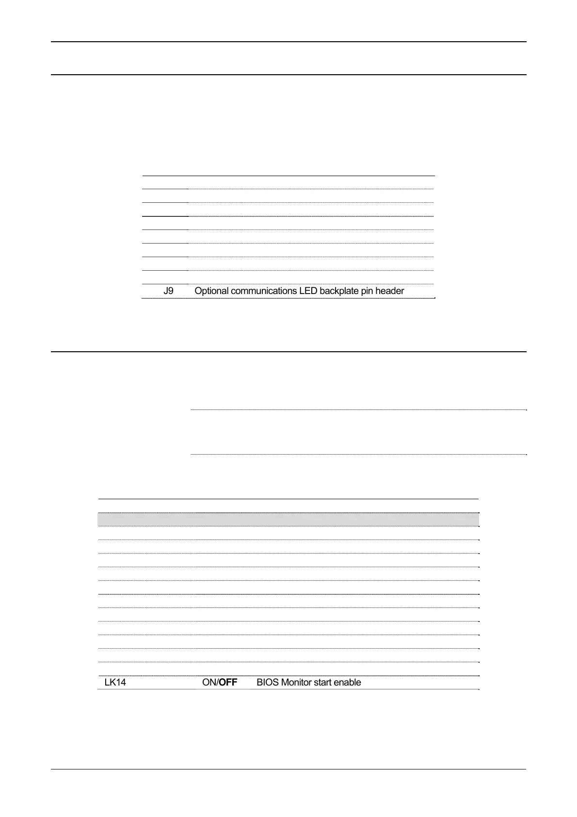
Table 3-8. Miscellaneous Device Connectors for the P152 CPU Module
Socket Description
J1 DIN Backplane Connector
J2 CPU cooling fan molex (12 VDC)
J3 PC/104 expansion bus (16- bit)
J4 Additional plug-in battery molex 3.6 V dc
J5 IDE Hard disk pin header
J6 Altera serial programming pin header (factory use only)
J7 Keyboard and mouse pin header
J8 Security bit link (Off = Level 1 Security Disabled)
J9 Optional communications LED backplate pin header
3.5 CPU Bit Links (Jumpers)
Table 3-9 shows the CPU bit links (or “jumpers”). This information is
for identification purposes only. Do not modify these settings, unless
told to do so by the factory.
Note: The position values shown in boldface are the default
configuration settings, which may not apply to your specific
configuration.
Table 3-9. CPU Bit Links
Jumper (Link) Position Description
LK1 & LK2 Not Used
CPU & RADISYS
LK3 ON/OFF Voltage Selection (On = 5 V, Off = 3.3 V)
LK4 ON/OFF Internal Real Time Clock enable
LK5 ON/OFF Internal keyboard & mouse disable
LK6 ON/OFF 8 bit (Off) or 16 bit (On) BIOS
LK7 ON/OFF 7 channel (On) or 2 channel (Off) DMA operation
LK8 ON/OFF All interrupts available via MUX (Multiplex)
LK9 ON/OFF EIDE parity (Off) or DRAM (On) supported
LK10 ON/OFF CS_USR1# (On) or Refresh (Off) supported
LK11 ON/OFF COM1, COM2 supported: data & RTS/CTS only
LK12 ON/OFF COMCLK enable
LK13 ON/OFF Cold Start forced on power up
LK14 ON/OFF BIOS Monitor start enable
Revised Jan-07 CPU 3-9

 Loading...


