S600 Instruction Manual
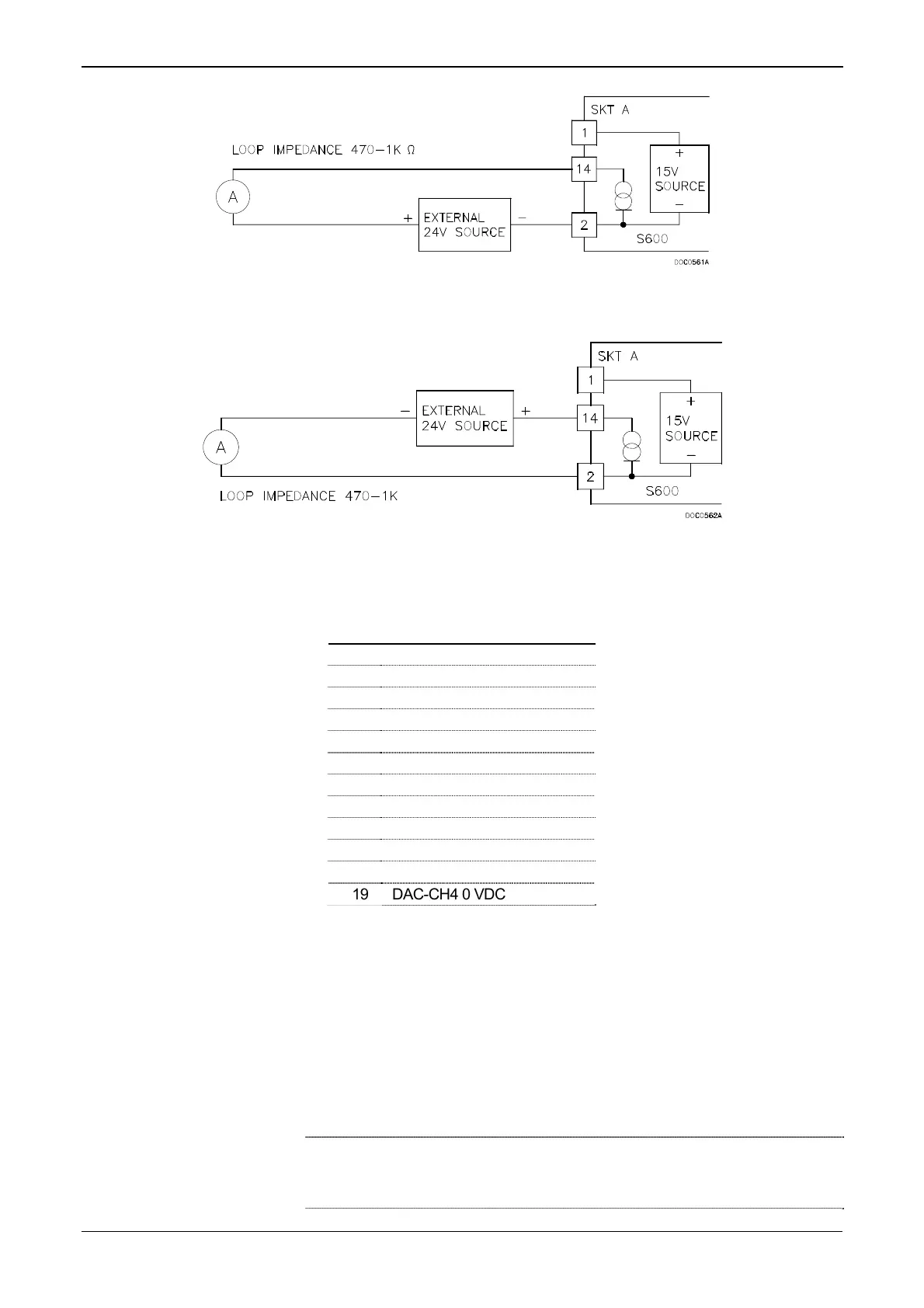
Figure 4-7. Analogue Output Schematic (Externally Powered Device)
Figure 4-8. Analogue Output Schematic (Externally Powered through S600)
Table 4-3. D/A Converter Output Pin Connections for SKT-A
Pin Function
1 DAC-CH1 +15 V SOURCE
14 DAC-CH1 SINK
2 DAC-CH1 0 VDC
15 DAC-CH2 +15 V SOURCE
3 DAC-CH2 SINK
16 DAC-CH2 0 VDC
4 DAC-CH3 +15 V SOURCE
17 DAC-CH3 SINK
5 DAC-CH3 0 VDC
18 DAC-CH4 +15 V SOURCE
6 DAC-CH4 SINK
19 DAC-CH4 0 VDC
4.1.3 Digital Inputs (DIGIN)
Each plug-in board provides 16 optically isolated digital inputs
(DIGIN). The digital inputs have been grouped into four banks of 4-off
single-ended inputs with one common feed. Refer to Figures 4-9 and 4-
10. The sample period is 500 milliseconds.
The DIGIN channels use the connectors labeled SKT-B and SKT-C,
which are located on the backplate of the P144 board. Refer to Tables
4-4 and 4-5 for the DIGIN pin connections.
Note: You must connect the feed lines (such as pin 17 on SKT-B) to a
24 Volts dc source. The DIGIN lines (such as pin 13 on SKT-B) expect
typical “open collector” (referenced to GND) connections.
4-6 I/O Revised Jan-07

 Loading...


