• Entrained gas will go up
2. Size the T-piece so that the meter tines are retracted 1 in (25 mm) from the main
pipe wall. For higher flow rates, increase this by 0.4 in (10 mm) for every 1 m/s
increase in the main flow rate.
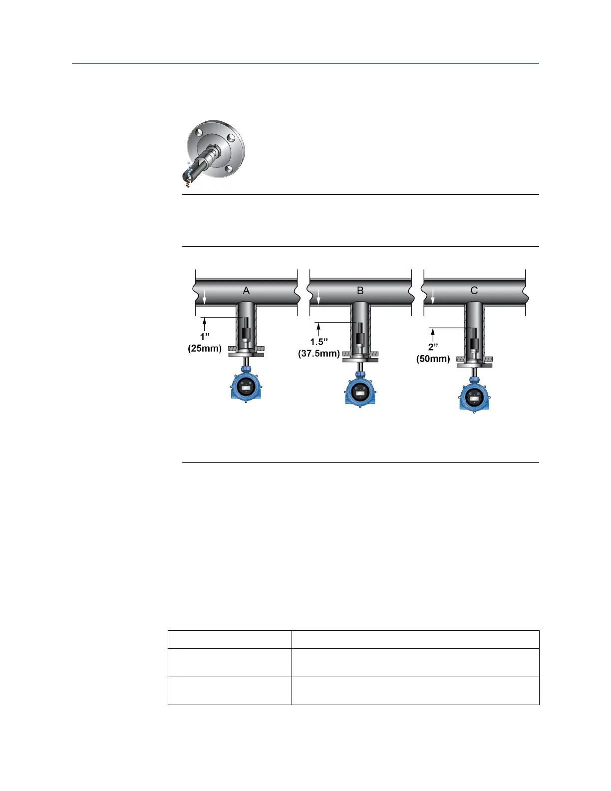
Figure 3-7: Pipe wall installation
A. Velocity ≤ 10 ft/sec (3 m/s)
B. 10 < velocity ≤ 13 ft/sec (4 m/s)
C. 13 < velocity ≤ 16 ft/sec (5 m/s)
3.2.2
Mount with a 3 in (76 mm) T-piece (flanged fitting)
Mount the FDM in a T-piece pipeline for slurry measurement applications. The T-piece
should be 3 in (76 mm) (DN80) and mounted at an angle to ensure that it will self-drain.
Flow velocity as low as 1.0m/s is acceptable, and preferred velocity is 3m/sec. Care should
be taken at flow velocities of 5m/sec, as there is an increased risk of the T-piece clogging.
Additional cleaning may be required.
Prerequisites
• 3 in (76 mm) T-piece (flanged) installations are recommended for processes with the
following conditions:
Flow
0.5 to 5 m/s (at the pipe wall)
Viscosity Up to 100 cP, or 1000 cP if the insertion distance does not
exceed 1 in (25 mm).
Temperature -58 °F (-50.0 °C) to 392 °F (200 °C)
-40 °F (-40.0 °C) to 392 °F (200 °C) in hazardous areas
Installation Manual Mounting
MMI-20020989 May 2019
Installation Manual 23