Figure 3-21: Meter placement (immersed in fluid)
5. Confirm the meter placement has allowed for the flexing of the tank lid to prevent
the meter from being pushed towards a tank wall or into the path of disturbed flow.
Figure 3-22: Meter placement (allowance for tank lid flexing)
A. 7.87 in (200 mm)
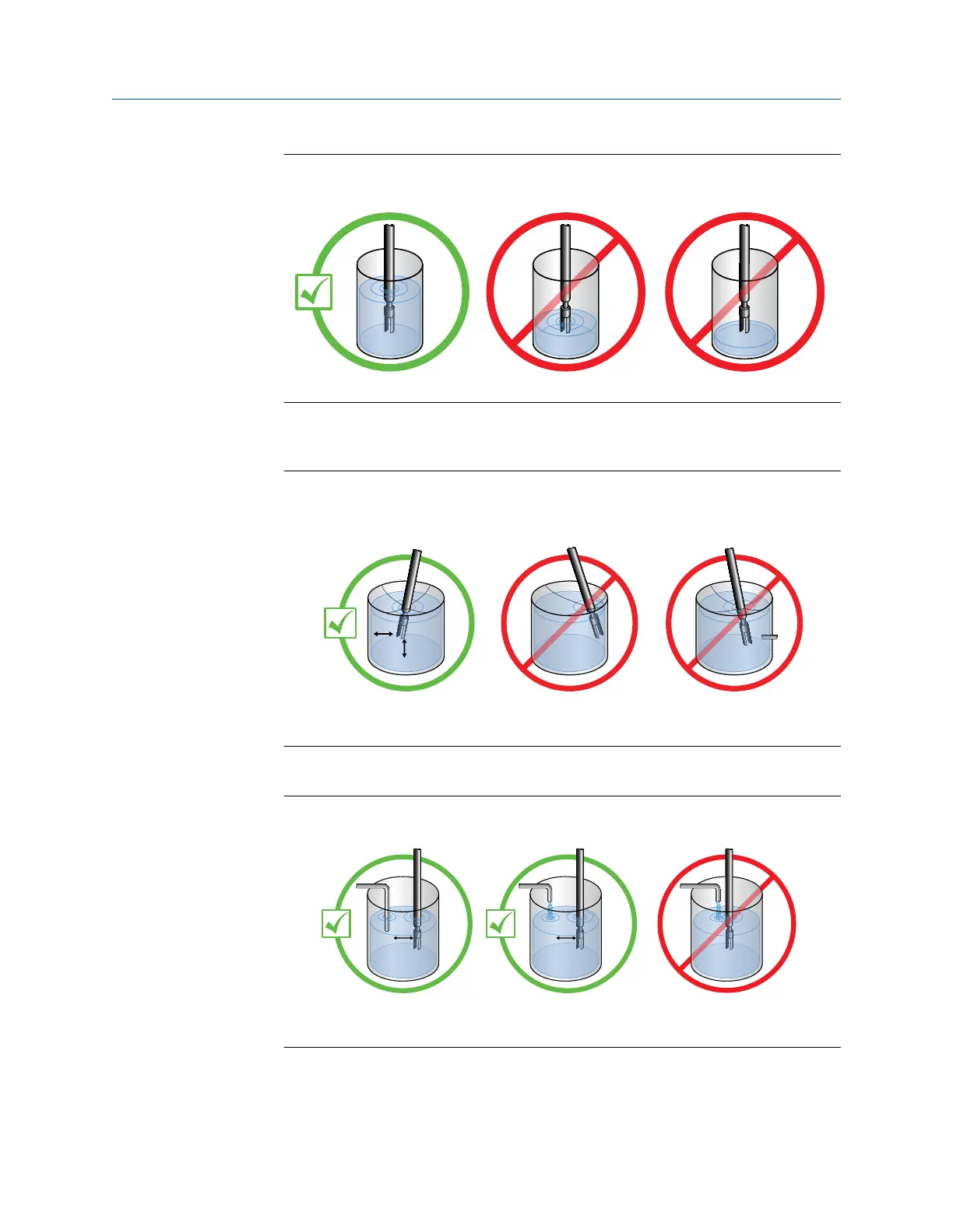
6. Confirm the meter tines are placed away from objects and disturbed flow.
Figure 3-23: Meter placement (distance from objects and disturbed flow)
A. 7.87 in (200 mm)
7. If flow exists, confirm the meter tines are aligned so that the flow is directed
towards or through the gap between the tines.
Mounting
Installation Manual
May 2019 MMI-20020989
34 Micro Motion Fork Density Meter