Procedure
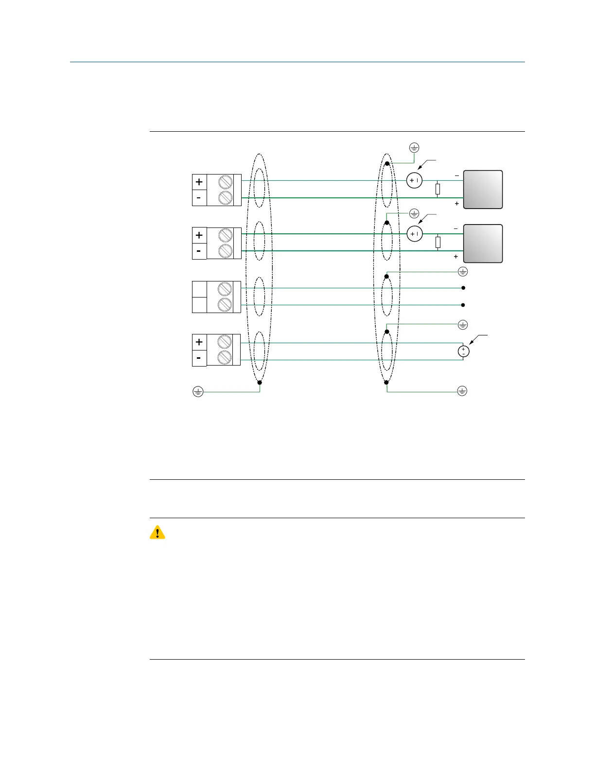
Wire to the appropriate output terminal and pins (see the following figure).
mA1+
HART
RS-485
PWR
mA2
AA
B
RS-485 A
RS-485 B
C
D
B
B
A
A
A
A. 24 VDC
B. R
load
(250 Ω resistance)
C. HART-compatible host or controller; and/or signal device
D. Signal device
Note
For operating the milliamp outputs with a 24V supply, a maximum total loop resistance of
657 Ω is allowed.
CAUTION
• To meet the EC Directive for Electromagnetic Compatibility (EMC), use a suitable
instrumentation cable to connect the meter. The instrumentation cable should have
individual screens, foil or braid over each twisted pair, and an overall screen to cover
all cores. Where permissible, connect the overall screen to earth at both ends (360°
bonded at both ends). Connect the inner individual screens at only the controller
end.
• Use metal cable glands where the cables enter the meter amplifier box. Fit unused
cable ports with metal blanking plugs.
Wiring Installation Manual
May 2019 MMI-20020989
40 Micro Motion Fork Density Meter