Option Description
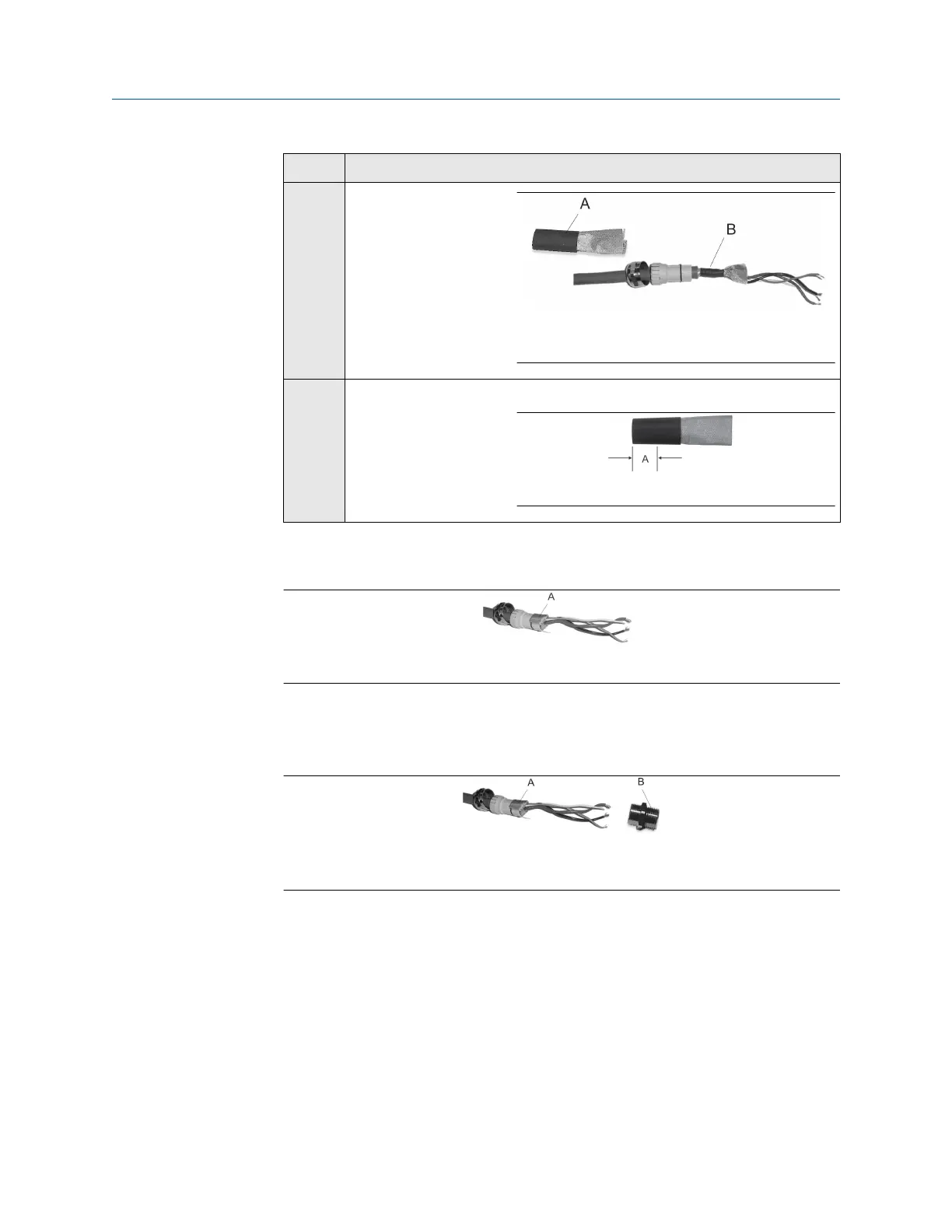
A. Shielded heat shrink
B. After heat is applied
M20
gland
type
Trim 0.3 in (8 mm).
A. Trim
8. Assemble the gland by folding the shield or braid back over the clamping insert and
0.125 in (3 mm) past the O-ring.
A. Shield folded back
9. Install the gland body into the conduit opening on the core processor housing.
10. Insert the wires through the gland body and tighten the gland nut onto the gland
body.
A. Shield folded back
B. Gland body
4.3.3
Processor wiring for the remote-mount 2700 fieldbus
option
The following figure illustrates how to connect the individual wires of a 4-wire cable to the
processor terminals. For detailed information on mounting and wiring to the remote-
mount 2700 fieldbus transmitter, see the transmitter installation manual.
Wiring
Installation Manual
May 2019 MMI-20020989
46 Micro Motion Fork Density Meter