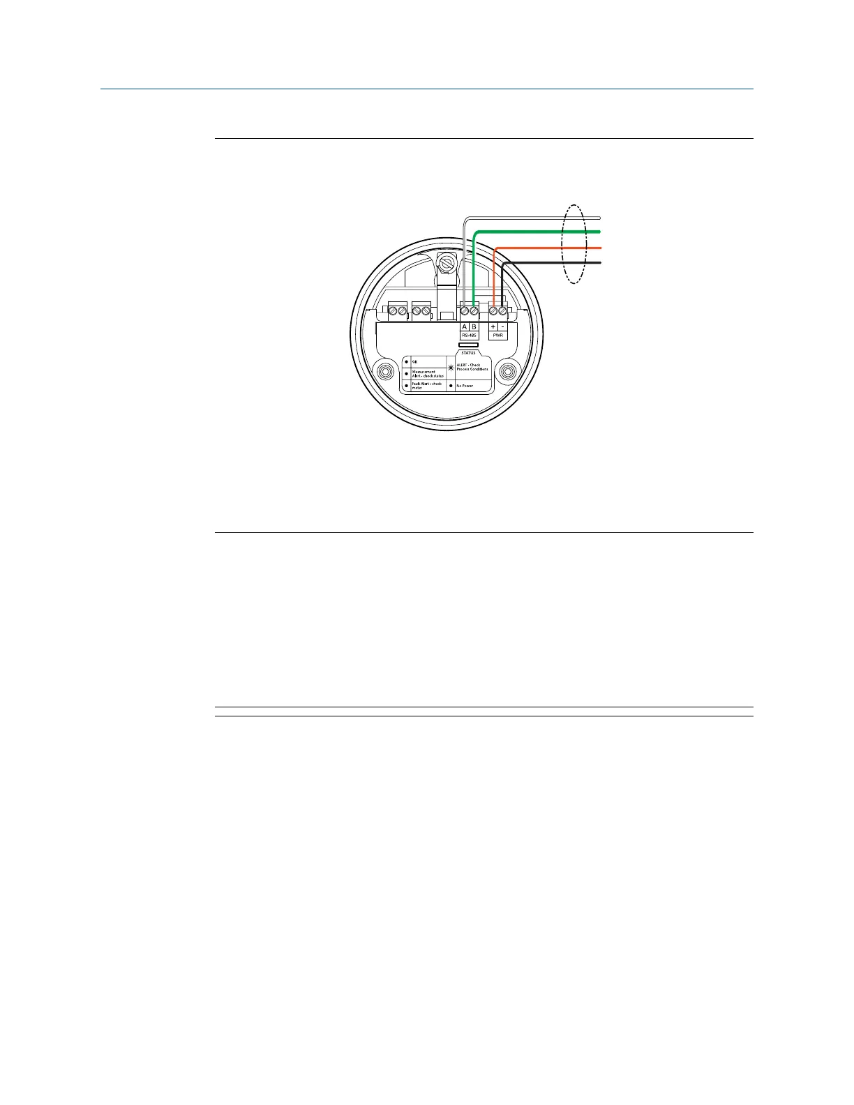
Figure 4-2: Processor (Modbus/RS-485) connections to the remote-mount 2700
fieldbus transmitter
A. White wire to RS-485/A terminal
B. Green wire to RS-485/B terminal
C. Red wire to Power supply (+) terminal
D. Black wire to Power supply (–) terminal
Important
• To meet the EC Directive for EMC (Electromagnetic Compatibility), it is recommended
that the meter be connected using a suitable instrumentation cable. The
instrumentation cable should have individual screens, foil or braid over each twisted
pair and an overall screen to cover all cores. Where permissible, the overall screen
should be connected to earth at both ends (360° bonded at both ends). The inner
individual screens should be connected at only one end, the controller end.
• Metal cable glands should be used where the cables enter the meter amplifier box.
Unused cable ports should be fitted with metal blanking plugs.
Installation Manual Wiring
MMI-20020989 May 2019
Installation Manual 47