Safety
Information
Product
information
Mechanical
Installation
Electrical
installation
Getting
started
Basic
parameters
Running the
motor
Optimization
SMARTCARD
operation
Onboard
PLC
Advanced
parameters
Technical
data
Diagnostics
UL
information
14 Mentor MP User Guide
www.controltechniques.com Issue: 3
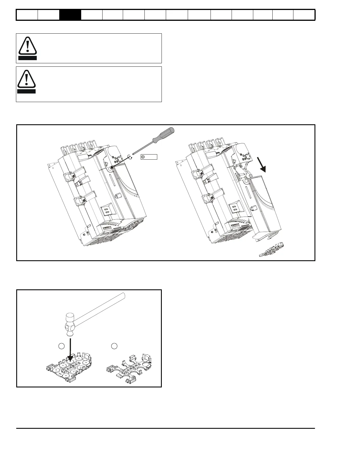
3.3 Terminal cover removal
3.3.1 Removing the terminal covers
The drive is installed with one control terminal cover.
Figure 3-1 Removing the control terminal cover (size 1 shown)
To remove the terminal cover, undo the screw and slide the terminal cover downwards.
When replacing the terminal covers the screw should be tightened with a maximum torque of 1 Nm (0.7 Ib ft).
3.3.2 Removing the finger-guard and break-outs
Figure 3-2 Removing the finger-guard break-outs
Place finger-guard on a flat solid surface and hit relevant break-outs with
hammer as shown (1). Continue until all required break-outs are removed
(2). Remove any flash / sharp edges once the break-outs are removed.
Isolation device
The AC supply must be disconnected from the drive using an
approved isolation device before any cover is removed from
the drive or before any servicing work is performed.
Stored charge
The drive contains capacitors that remain charged to a
potentially lethal voltage after the AC supply has been
disconnected. If the drive has been energized, the AC
supply must be isolated at least ten minutes before work
may continue.