Safety
Information
Product
information
Mechanical
Installation
Electrical
installation
Getting
started
Basic
parameters
Running the
motor
Optimization
SMARTCARD
operation
Onboard
PLC
Advanced
parameters
Technical
data
Diagnostics
UL
information
Mentor MP User Guide 143
Issue: 3 www.controltechniques.com
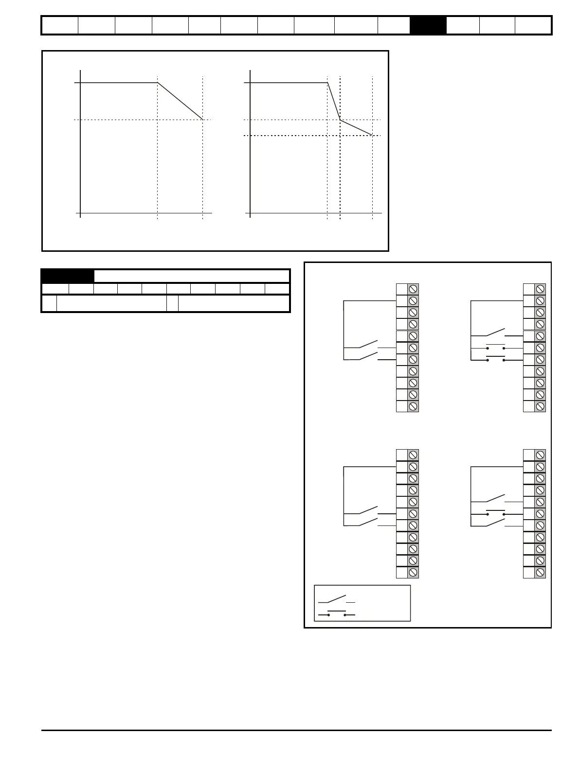
Figure 11-20 Current limit versus speed
11.22.5 Start / stop logic modes
This parameter is provided to allow the user to select several predefined
digital input routing macros to control the sequencer. When a value
between 0 and 3 is selected the drive processor continuously updates
the destination parameters for digital I/O T25, T26 and T27, and the
enable sequencer latching bit (Pr 6.40). When a value of 4 is selected
the destination parameters for these digital I/O and Pr 6.40 can be
modified by the user.
If Pr 6.04 is changed then a drive reset is required before the function of
T25, T26 or T27 will become active.
If Pr 6.04 has been set to a value of 0 to 3, then setting Pr 6.04 to 4 does
not automatically reconfigure terminals T25, T26 and T27 to their default
functions. To return terminals T25, T26 and T27 to their default
functions, one of the following operations should be performed.
• Drive defaults should be restored. See section 5.9 Restoring
parameter defaults on page 61 for details.
• Manually set Pr 6.04 to 4, Pr 6.40 to 0, Pr 8.22 to 10.33, Pr 8.23 to
6.30, and Pr 8.24 to 6.32.
Figure 11-21 Digital input connections when Pr 6.04 is set to 0 to 3
Pr
4.07
Pr
4.29
Pr
4.27
Pr
1.06
One taper
Pr
4.07
Pr
4.29
Pr
4.27
Two tapers
Pr
4.28
Pr
1.06
Pr
4.30
Current limit versus speed
6.04 Start / stop logic select
RW Uni US
Ú
0 to 4
Ö
0
30
31
28
29
26
27
24
25
23
21
22
+24V
Run Fwd
Run Rev
Pr 6.04 is set to 0
30
31
+24V
Run
Fwd/Rev
Pr 6.04 is set to 2