Safety
Information
Product
information
Mechanical
Installation
Electrical
installation
Getting
started
Basic
parameters
Running the
motor
Optimization
SMARTCARD
operation
Onboard
PLC
Advanced
parameters
Technical
data
Diagnostics
UL
information
26 Mentor MP User Guide
www.controltechniques.com Issue: 3
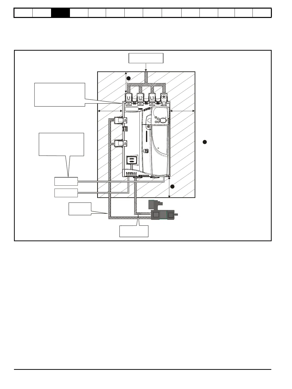
3.6 Enclosure
3.6.1 Enclosure layout
Please observe the clearances in the diagram below taking into account any appropriate notes for other devices / auxiliary equipment when planning
the installation.
Figure 3-17 Enclosure layout
3.6.2 Enclosure sizing
Refer to section 12.1.2 Typical short-term overload limits on page 145
for drive losses.
Add the dissipation figures for each drive that is to be installed in the
enclosure.
Add the power dissipation figures for each EMC filter that is to be
installed in the enclosure.
Calculate the total heat dissipation (in Watts) of any other equipment to
be installed in the enclosure.
Add the figures of all of the above to get a total heat dissipation figure (in
Watts) for the equipment in the enclosure.
Calculating the size of a sealed enclosure
The enclosure transfers internally generated heat into the surrounding
air by natural convection. The larger the surface area of the enclosure
walls, the better is the dissipation capability. Only the surfaces of the
enclosure that are not in contact with a wall or floor can dissipate heat.
Calculate the minimum required unobstructed surface area A
e
for the
enclosure from:
Where:
A
e
Unobstructed surface area in m
2
(1 m
2
= 10.9 ft
2
)
T
ext
Maximum expected temperature in
o
C outside the
enclosure
T
int
Maximum permissible temperature in
o
C inside the
enclosure
P Power in Watts dissipated by all heat sources in the
enclosure
k Heat transmission coefficient of the enclosure material
in W/m
2
/
o
C
Example
To calculate the size of an enclosure for the following:
• Two MP25A4 models operating under full load conditions
• Maximum ambient temperature inside the enclosure: 40°C
• Maximum ambient temperature outside the enclosure: 30°C
Dissipation of each drive: 125W
Dissipation from other heat generating equipment in the enclosure. 11W
(max).
Total dissipation: 2 x (125 + 11) = 272W
Enclosure
AC supply contactor,
External
controller
Ensure minimum clearances
are maintained for the drive.
Forced or convection air-flow
must not be restricted by any
object or cabling
Auxillary
supply
Signal cables
Plan for all signal cables
to be routed at least
300mm (12in) from the
drive and any power cable
Armature
connection
cable
Field
1) Power cabling must be at
least 100mm (4in) from the
drive in all directions
2) Ensure direct metal contact
at drive and filter mounting
points (any paint must be
removed)
100mm for Size 1 drives
200mm for Size 2A/2B drives
leave a clearance of 100mm
A
e
P
kT
int
T
ext
–()
----------------------------------------
=