Safety
Information
Product
information
Mechanical
Installation
Electrical
installation
Getting
started
Basic
parameters
Running the
motor
Optimization
SMARTCARD
operation
Onboard
PLC
Advanced
parameters
Technical
data
Diagnostics
UL
information
142 Mentor MP User Guide
www.controltechniques.com Issue: 3
the maximum speed must be limited by the drive.
3: Coiler/uncoiler mode
Positive final speed demand: a positive resultant torque will give torque
control with a positive speed limit defined by the final speed demand. A
negative resultant torque will give torque control with a negative speed
limit of -5rpm.
Negative final speed demand: a negative resultant torque will give
torque control with a negative speed limit defined by the final speed
demand. A positive resultant torque will give torque control with a
positive speed limit of +5rpm.
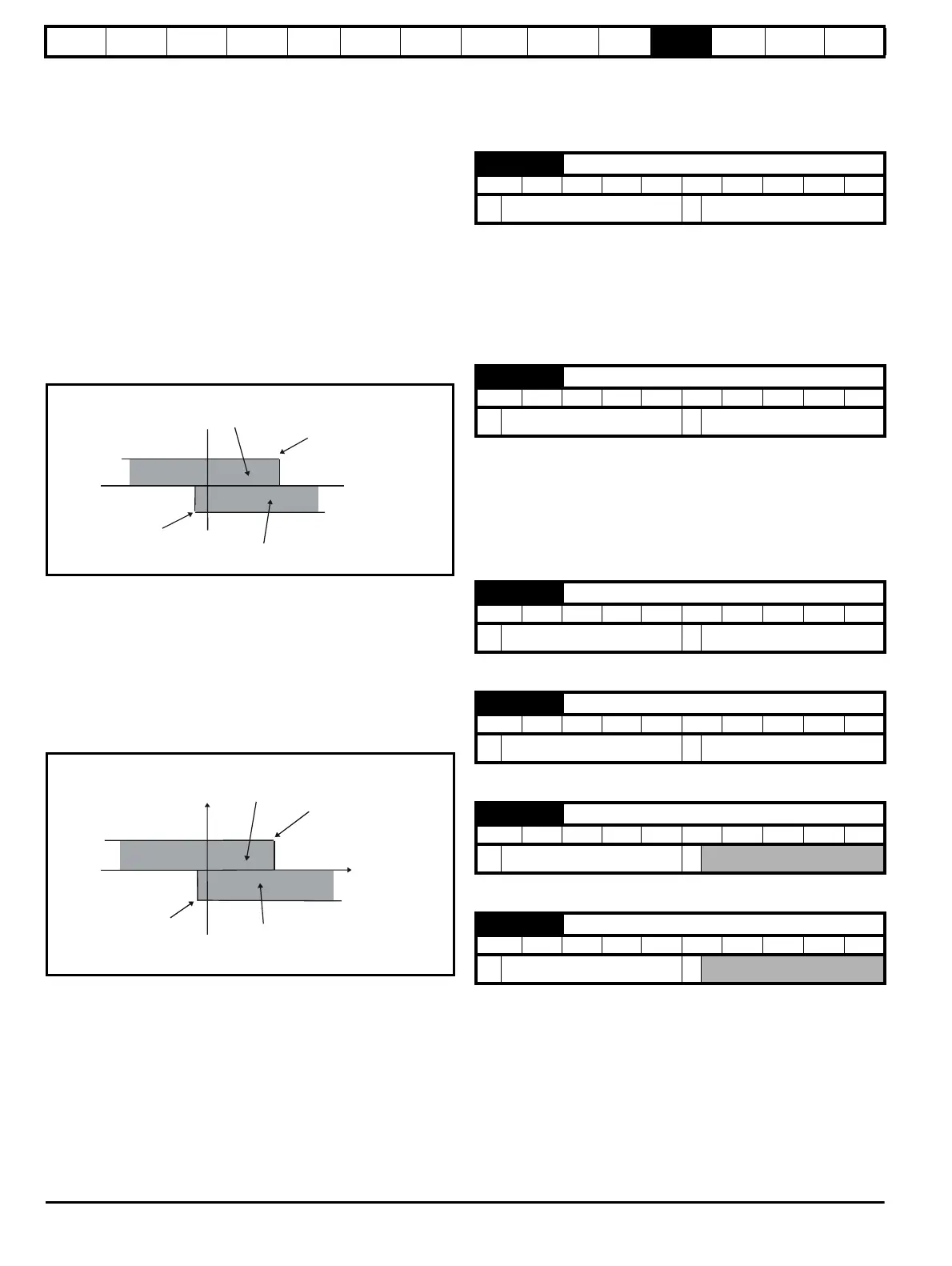
Example of coiler operation:
This is an example of a coiler operating in the positive direction. The final
speed demand is set to a positive value just above the coiler reference
speed. If the resultant torque demand is positive the coiler operates with
a limited speed, so that if the material breaks the speed does not exceed
a level just above the reference. It is also possible to decelerate the
coiler with a negative resultant torque demand. The coiler will decelerate
down to -5rpm until a stop is applied. The operating area is shown in the
following diagram:
Example of uncoiler operation:
This is an example for an uncoiler operating in the positive direction. The
final speed demand should be set to a level just above the maximum
normal speed. When the resultant torque demand is negative the
uncoiler will apply tension and try and rotate at 5rpm in reverse, and so
take up any slack. The uncoiler can operate at any positive speed
applying tension. If it is necessary to accelerate the uncoiler a positive
resultant torque demand is used. The speed will be limited to the final
speed demand. The operating area is the same as that for the coiler and
is shown below:
:
4: Speed control with torque feed-forward
The drive operates under speed control, but a torque value may be
added to the output of the speed controller. This can be used to
improve the regulation of systems where the speed loop gains need
to be low for stability.
11.22.4 Current limit tapers
With some motors the commutation limit of the motor requires that the
maximum armature current be reduced at higher speeds, the current
limit tapers can be used to provide this speed dependent current limit.
Sets a threshold value of speed feedback, beyond which Pr 4.31
changes to 1 to indicate that the threshold has been exceeded, and is
the starting point for taper 2, if implemented. The current limit reduces,
as a function of speed, to an end point defined by Pr 4.29.
The output of the taper block controls Pr 4.18.
If only 1 taper is used, it must be taper 1. If both are used, taper 1 must
be first. Refer to Figure 11-20.
Sets a threshold value of speed feedback, beyond which Pr 4.32
changes to 1 to indicate that the threshold has been exceeded, and is
the starting point for taper 2, if implemented. The current limit reduces,
as a function of speed, to an end point defined by Pr 4.30.
The output of the taper block controls Pr 4.18.
If only one taper is used, it must be taper 1. If both are used, taper 1
must be first. Refer to Figure 11-20.
Defines the current at the end of taper 1.
Defines the current at the end of taper 2.
Indicates when speed feedback has exceeded threshold 1.
Indicates when speed feedback has exceeded threshold 2.
Final speed
demand
Area for coiler operation, speed
limited to ref and positve torque
Area for decelerating the coiler, reverse
speed limited and negative torque
-5rpm
Speed
Torque
-5rpm
Area for normal uncoiler
operation: negative torque,
limited to low speed in reverse
Speed reference
Area for accelerating
uncoiler: positive torque,
limited speed
Speed
Tor que
4.27 Current taper 1 threshold
RW Uni US
Ú
0.0 to 10,000.0 rpm
Ö
10,000 rpm
4.28 Current taper 2 threshold
RW Uni US
Ú
0.0 to 10,000.0 rpm
Ö
10,000 rpm
4.29 Current taper 1 end point
RW Uni US
Ú
0 to 1000.0 %
Ö
1000.0 %
4.30 Current taper 2 end point
RW Uni US
Ú
0 to 1000.0 %
Ö
1000.0 %
4.31 Taper threshold 1 exceeded
RO Bit
Ú
OFF (0) or On (1)
Ö
4.32 Taper threshold 2 exceeded
RO Bit
Ú
OFF (0) or On (1)
Ö