Safety
Information
Product
information
Mechanical
Installation
Electrical
installation
Getting
started
Basic
parameters
Running the
motor
Optimization
SMARTCARD
operation
Onboard
PLC
Advanced
parameters
Technical
data
Diagnostics
UL
information
152 Mentor MP User Guide
www.controltechniques.com Issue: 3
Table 12-12 Auxiliary wiring for size 1 drives
Notes for IEC 60364:
IEC 60364-5-52 use installation method B2, Table A.52-4 for three loaded conductors, PVC insulation 30°C and apply derating factor for 40°C from
Table A.52-14 (0.87 for PVC).
Notes for UL508C:
Either 60°C or 75°C cable can be used. Ampacities as per table 40.3 as described in the UL508C standard.
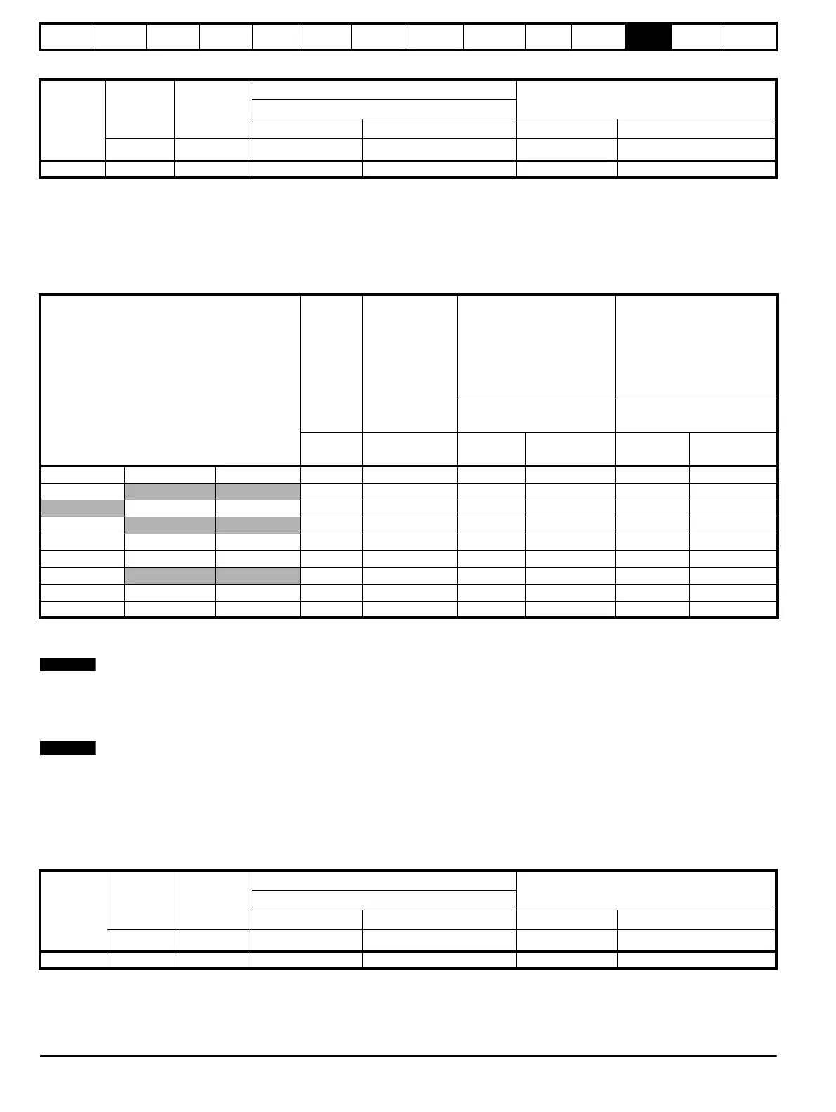
Table 12-13 Typical cable sizes for size 2 drives
* Values are beyond the mechanical design of the drive. At this power level it may be prudent to consider bus-bars.
Notes for IEC 60364:
1. IEC 60364-5-52 Table A 52-12 F method column 5 = Single core cable in free air.
2. IEC 60364-5-52 table A52-14 correction factor for ambient air temperature others than 30°C.
3. IEC 60364-5-52 table A52-17 item 4 correction factor for groups of more than one circuit or more than one multi-core cable placed on a single
layer on a perforated tray.
Notes for US National Electrical Code:
1. Table 310.17 allowable ampacities of single-insulated conducted rated 0 through 2000V in free air, based on ambient air temperature of 30°C
(87°F).
2. Derating factor of 0.88 is applied for 40°C to the 75°C cable column. Table 310.17 is based on 30°C (86°F) ambient air temperature.
3. NEC 2005 edition Table 310.15(B)(2)(a) shows the adjustment factors for more than three current-carrying conductors in a race way or cable, for
4-6 current-carrying conductors 0.80 derating factor is applied.
Table 12-14 Auxilliary wiring for size 2 drives
Notes for IEC 60364:
IEC 60364-5-52 use installation method B2, Table A.52-4 for three loaded conductors, PVC insulation 30°C and apply derating factor for 40°C from
Table A.52-14 (0.87 for PVC).
Notes for UL508C: Either 60°C or 75°C cable can be used. Ampacities as per table 40.3 as described in the UL508C standard.
Frame
size
Maximum
input
current
Continuous
output
current
IEC 60364-5-52 Table A52-4 Column B2
UL 508C
Column B2 derated by 0,87 of PVC at 40
E1, E3 size F+, F- , L11 & L12 size E1, E3 size F+, F- , L11 & L12 size
AA
mm
² mm² mm² mm²
1 13 8 2.5 1.5 14 AWG 14 AWG
Model
Maximum
input
current
Continuous
output current
IEC 60364-5-52 Table A52-
12 Column 5 derated by
0.91 for 40°C XLPE cables
(IEC 60364-5-52 table A52-
14) and 0.77 for cables
bunching (IEC 60364-5-52
table A52-17 item 4)
US National
Electrical Code
90°C cables at 40°C
ambient
75°C cable at 40°C ambient
AA
Input size
mm²
Output size
mm²
Input cables
Kcmil
Output cables
Kcmil
MP350A4(R) MP350A5(R) MP350A6(R) 313 350 120 150 350 400
MP420A4(R) 375 420 150 185 400 500
MP470A5(R) MP470A6(R) 420 470 185 240 500 600
MP550A4(R) 492 550 300 2 x 185 2 x 300 2 x 350
MP700A4(R) MP700A5(R) MP700A6(R) 626 700 2 x 150 2 x 150 2 x 500 2 x 600
MP825A4(R) MP825A5(R)
MP825A6(R) 738 825 2 x 185 2 x 240 2 x 600 3 x 350
MP900A4(R) 805 900 2 x 185 2 x 240 3 x 350 3 x 400
MP1200A4(R) MP1200A5(R) MP1200A6(R) 1073 1200 2 x 300 3 x 240 3 x 600 4 x 400
MP1850A4(R) MP1850A5(R) MP1850A6(R) 1654 1850 4 x 240 4 x 300 * *
Frame size
Maximum
input
current
Continuous
output
current
IEC 60364-5-52 Table A52-4 Column B2
UL 508C
Column B2 derated by 0,87 of PVC at 40
E1, E3 size F+, F- , L11 & L12 size E1, E3 size F+, F- , L11 & L12 size
AA
mm
² mm² mm² mm²
2 23 20 6 4 10 AWG 10 AWG