12
Safety Manual
00809-0200-5100, Rev GB
Installation and Configuration
February 2017
Installation and Configuration
4.1.1 Wiring diagram
Figure 4-1. Wiring diagram for Rosemount 2410 and Rosemount 5900 with SIL option
See installation drawings as specified in Table 4-1 on page 13 for more information on wiring the
2410 Tank Hub and the 5900 Radar Level Gauge.
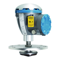
Rosemount 5900
Radar Level Gauge
Rosemount 2410
Tank Hub
SIL Alarm Relay Output
SIL Alarm
Ta nk bus
Intrinsically Safe (Exi)Non-Intrinsically Safe
(Exd/Exe)
Power
Supply
Configuration (not
part of the safety
function)
 Loading...


