14
Safety Manual
00809-0200-5100, Rev GB
Installation and Configuration
February 2017
Installation and Configuration
4.1.2 The Rosemount 5900 terminal block
Terminal block connections for the Rosemount 5900 with SIL option:
Figure 4-2. 5900 terminal compartment
Table 4-2. 5900 terminal block connections with SIL alarm output
See “Wiring diagram” on page 12 for information on how to connect a Rosemount 5900 Radar
Level Gauge to a Rosemount 2410 Tank Hub in a Rosemount Tank Gauging Safety System.
Connection SIL Safety System
X1: Primary Tankbus in Intrinsically safe Tankbus input, power and communication
X2: Alarm SIL alarm output
(connect to Exi terminal block on Rosemount 2410 Tank Hub)
Note! There are different terminal blocks for SIL 2 and SIL 3.
X3: Primary Tankbus out Optional jumpers between X3 and X4 for connection to second level
gauge when using the 2-in-1 version of the Rosemount 5900 for SIL 3
installations. No jumpers are used for SIL 2.
X4: Secondary Tankbus in
Test terminals Test terminals for temporary connection of a handheld communicator
such as the Rosemount 475 Field Communicator
Ground terminals, internal
SIL Alarm
Ta nk bus
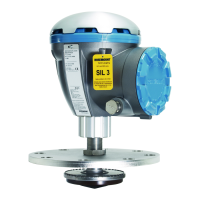
Rosemount 5900 Radar Level Gauge
Test terminals
FB+
FB-
2-in-1: jumpers between X3
and X4 for connection to
second level gauge
Label that indicates SIL Level SIL 3 or SIL 2
 Loading...


