Reference Manual
00809-0100-4840, Rev. BA
July 2008
1-3
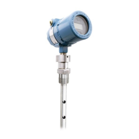
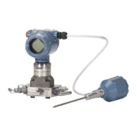
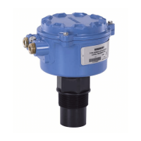
Rosemount 3100 Series
SERVICE SUPPORT To expedite the return process outside of the United States, contact the
nearest Emerson Process Management representative.
Within the United States, call the Emerson Process Management Instrument
and Valves Response Center using the toll-free number 1-800-654-RSMT
(7768). This center, available 24 hours a day, will assist you with any needed
information or materials.
The center will ask for product model and serial numbers, and will provide a
Return Material Authorization (RMA) number. The center will also ask for the
process material to which the product was last exposed.
Emerson Process Management Instrument and Valves Response Center
representatives will explain the additional information and procedures
necessary to return goods exposed to hazardous substance can avoid injury if
they are informed of and understand the hazard. If the product being returned
was exposed to a hazardous substance as defined by OSHA, a copy of the
required Material Safety Data Sheet (MSDS) for each hazardous substance
identified must be included with the returned goods.
 Loading...
