Safety
Information
Introduction
Product
information
System
design
Mechanical
installation
Electrical
installation
Getting
started
Optimisation Parameters
Technical
data
Component
sizing
Diagnostics
46 Unidrive SP Regen Installation Guide
www.controltechniques.com Issue Number: 2
5.3 Regen component dimensions
The dimensions listed are for the following items:
• Regen inductor
• Switching frequency filter inductor
• Switching frequency filter capacitor
•Varistors
• External charging resistor (used in multiple motoring configurations)
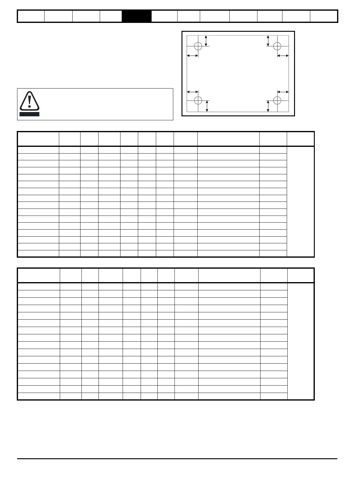
5.3.1 Regen inductor
Figure 5-1 Top view of fixing type A
Table 5-1 200V Regen inductor specifications
Table 5-2 400V Regen inductor specifications
The following regen inductors can produce significant losses
with a normal operating temperature in the region of 170°C
dependant upon the ambient temperature. Location of the
regen inductor should be considered to avoid damage to heat
sensitive components or create a fire risk.
CAUTION
y
x
y
y
x
xx
y
Inductor part
number
Amps mH
Losses
W
L
mm
D
mm
H
mm
Weight
kg
Fixing centres (x * y)
mm
Fixing
mm
Fixing
type
4401-0310 9.6 3.5 71 215 180 200 10 120 x 140 9
A
4401-0311 11.0 2.7 72 215 180 200 11 120 x 140 9
4401-0312 15.5 2.2 116 215 180 200 12 120 x 140 9
4401-0313 22 1.6 157 215 180 200 15 120 x 140 9
4401-0314 31 1.10 193 270 180 240 17 160 x 140 9
4401-0315 42 0.81 200 270 200 240 24 160 x 160 9
4401-0316 56 0.6 264 325 220 320 32 200 x 180 11
4401-0317 68 0.5 299 325 220 320 33 200 x 180 11
4401-0318 80 0.4 298 325 220 320 39 200 x 180 11
4401-0319 105 0.32 338 370 260 360 55 240 x 220 11
4401-0320 130 0.26 394 375 280 360 65 240 x 240 11
4401-0321 156 0.22 475 395 280 360 77 240 x 240 11
4401-0322 192 0.18 526 395 280 360 97 240 x 240 11
4401-0323 250 0.14 610 430 300 410 110 280 x 260 11
4401-0324 312 0.11 776 430 300 410 120 280 x 260 11
4401-0325 350 0.10 863 490 320 480 130 320 x 260 11
Inductor part
number
Amps mH
Losses
W
L
mm
D
mm
H
mm
Weight
kg
Fixing centres (x * y)
mm
Fixing
mm
Fixing
type
4401-0001 9.5 6.32 125.0 200 180 215 12 120 x 140 9
A
4401-0002 12 5.00 146.0 200 180 215 14 120 x 140 9
4401-0003 16 3.75 175.0 240 180 270 17 160 x 140 9
4401-0004 25 2.40 210.0 240 180 270 24 160 x 160 9
4401-0005 34 1.76 285.0 320 220 325 32 200 x 180 11
4401-0006 40 1.50 310.0 320 220 325 33 200 x 180 11
4401-0007 46 1.30 320.0 320 220 325 39 200 x 180 11
4401-0008 60 1.00 345.0 360 260 370 55 240 x 220 11
4401-0009 70 0.78 415.0 360 260 370 65 240 x 240 11
4401-0010 96 0.63 515.0 360 260 370 75 240 x 240 11
4401-0011 124 0.48 585.0 360 260 370 95 240 x 240 11
4401-0012 156 0.38 645.0 410 300 430 110 280 x 260 11
4401-0013 180 0.33 775.0 410 300 430 120 280 x 260 11
4401-0014 200 0.30 845.0 480 320 490 130 320 x 260 11
4401-0015 300 0.20 1760.0 480 320 490 140 320 x 240 11
4401-0205-00 350 0.16 2169.0 500 320 570 165 320 x 260 11