Safety
Information
Introduction
Product
information
System
design
Mechanical
installation
Electrical
installation
Getting
started
Optimisation Parameters
Technical
data
Component
sizing
Diagnostics
196 Unidrive SP Regen Installation Guide
www.controltechniques.com Issue Number: 2
10.4 Component data
The following parts may be used:
• Motoring drive
• Regen drive
• Regen inductor
• Softstart resistor
• Switching frequency filter (optional)
• EMC filter (optional)
•Varistors
•Fusing
• Contactors
• Overloads
In addition to the above the additional items are also required to
assemble a Unidrive SP Regen Brake Resistor replacement system:
• Isolating transformer
• DC bus diode
10.4.1 Regen inductors
The regen inductor duty is very arduous, and therefore, correct
component selection is critical. The most sensitive aspect being the
inductor linearity. Only inductors specified in this installation guide
should be used.
The regen inductor supports the difference between the PWM voltage
from the Regen drive and the sinusoidal voltage from the supply. One
three-phase regen inductor is required per Regen drive.
Each regen inductor is fitted with a 170°C thermistor mounted in the
centre coil. The thermistor is set to 170°C at which point the resistance is
1000Ω, beyond 170°C a rapid rise in resistance will be seen.
If the permissible cable lengths are exceeded additional cooling may be
required for the regen inductors, refer to section 4.4.4 Cable length on
page 41.
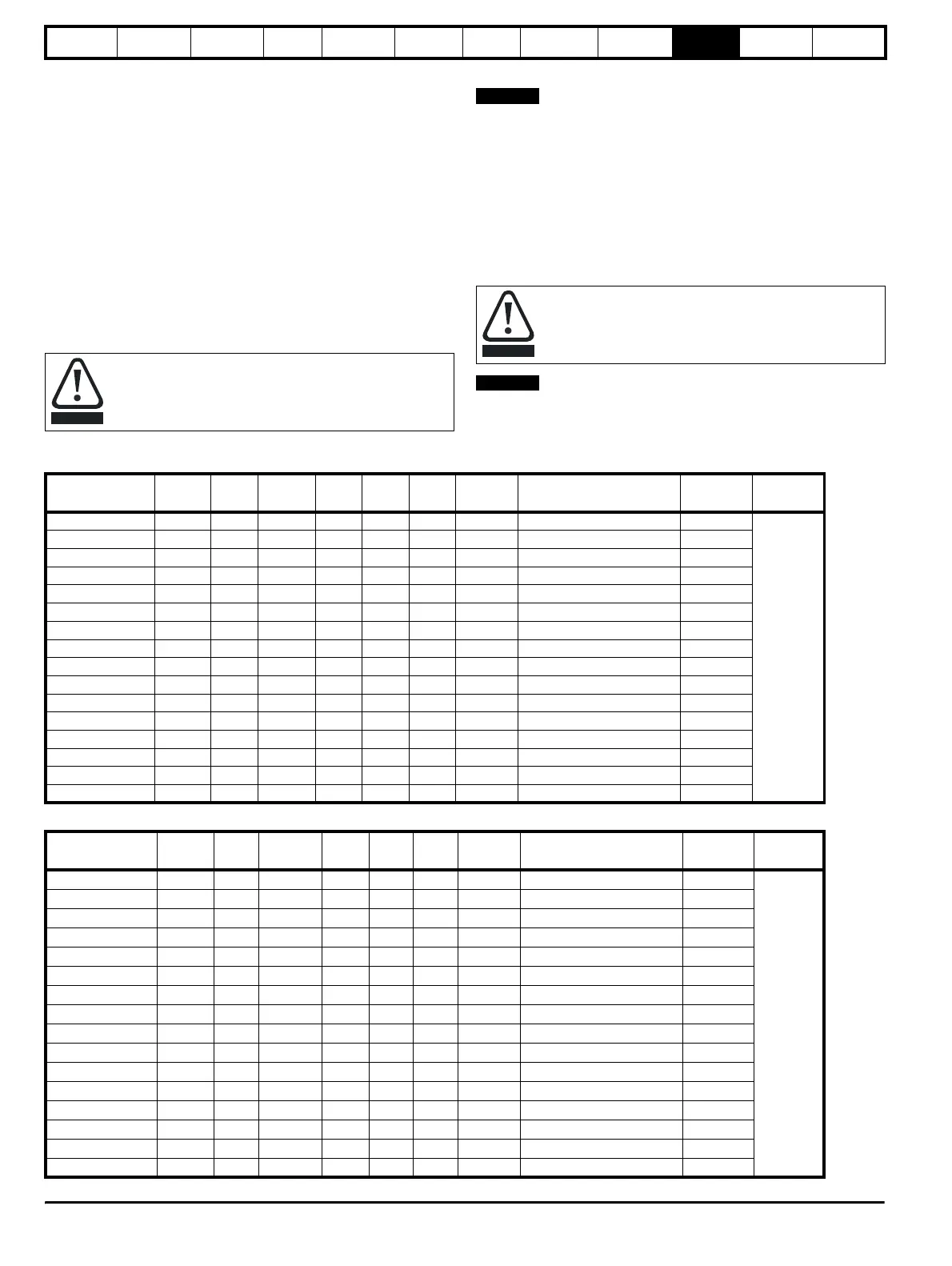
Table 10-21 200V Regen inductor specifications
Table 10-22 400V Regen inductor specifications
The internal EMC filter must be removed from drive.
CAUTION
The regen inductors have a normal operating temperature of
approximately 170°C depending upon the ambient and the
motor cable lengths. Care must be taken so that this does not
create a fire risk.
NOTE
CAUTION
NOTE
Inductor part
number
Amps mH
Losses
W
L
mm
D
mm
H
mm
Weight
kg
Fixing centres (x * y)
mm
Fixing
mm
Fixing
type
4401-0310 9.6 3.5 71 215 180 200 10 120 x 140 9
A
4401-0311 11.0 2.7 72 215 180 200 11 120 x 140 9
4401-0312 15.5 2.2 116 215 180 200 12 120 x 140 9
4401-0313 22 1.6 157 215 180 200 15 120 x 140 9
4401-0314 31 1.10 193 270 180 240 17 160 x 140 9
4401-0315 42 0.81 200 270 200 240 24 160 x 160 9
4401-0316 56 0.6 264 325 220 320 32 200 x 180 11
4401-0317 68 0.5 299 325 220 320 33 200 x 180 11
4401-0318 80 0.4 298 325 220 320 39 200 x 180 11
4401-0319 105 0.32 338 370 260 360 55 240 x 220 11
4401-0320 130 0.26 394 375 280 360 65 240 x 240 11
4401-0321 156 0.22 475 395 280 360 77 240 x 240 11
4401-0322 192 0.18 526 395 280 360 97 240 x 240 11
4401-0323 250 0.14 610 430 300 410 110 280 x 260 11
4401-0324 312 0.11 776 430 300 410 120 280 x 260 11
4401-0325 350 0.10 863 490 320 480 130 320 x 260 11
Inductor part
number
Amps mH
Losses
W
L
mm
D
mm
H
mm
Weight
kg
Fixing centres (x * y)
mm
Fixing
mm
Fixing
type
4401-0001 9.5 6.32 125.0 200 180 215 12 120 x 140 9
A
4401-0002 12 5.00 146.0 200 180 215 14 120 x 140 9
4401-0003 16 3.75 175.0 240 180 270 17 160 x 140 9
4401-0004 25 2.40 210.0 240 180 270 24 160 x 160 9
4401-0005 34 1.76 285.0 320 220 325 32 200 x 180 11
4401-0006 40 1.50 310.0 320 220 325 33 200 x 180 11
4401-0007 46 1.30 320.0 320 220 325 39 200 x 180 11
4401-0008 60 1.00 345.0 360 260 370 55 240 x 220 11
4401-0009 70 0.78 415.0 360 260 370 65 240 x 240 11
4401-0010 96 0.63 515.0 360 260 370 75 240 x 240 11
4401-0011 124 0.48 585.0 360 260 370 95 240 x 240 11
4401-0012 156 0.38 645.0 410 300 430 110 280 x 260 11
4401-0013 180 0.33 775.0 410 300 430 120 280 x 260 11
4401-0014 200 0.30 845.0 480 320 490 130 320 x 260 11
4401-0015 300 0.20 1760.0 480 320 490 140 320 x 240 11
4401-0205-00 350 0.16 1500 500 320 570 165 320 x 260 11