Safety
Information
Introduction
Product
information
System
design
Mechanical
installation
Electrical
installation
Getting
started
Optimisation Parameters
Techn i cal
data
Component
sizing
Diagnostics
68 Unidrive SP Regen Installation Guide
www.controltechniques.com Issue Number: 2
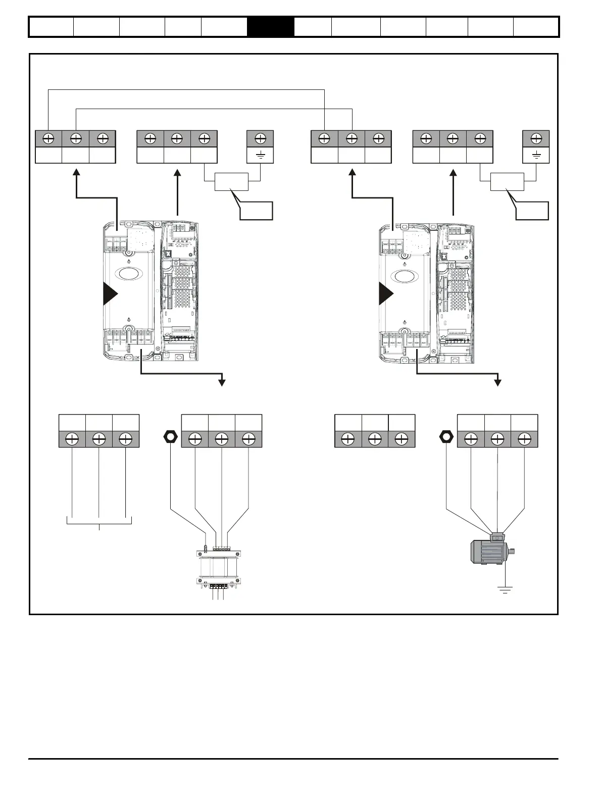
Figure 6-3 Unidrive SP size 3 power connections
On Unidrive SP size 2 and 3, the high current DC connections must
always be used when using a braking resistor, supplying the drive from
DC (low voltage 48V or high voltage) or using the drive in a parallel DC
bus system. The low current DC connection is used only to connect the
internal EMC filter.
See Figure 6-9 for further information on ground connections.
L2L1 L3 U V WPE
AC supply connections
BRDC1 DC2
D
connections
(High current DC to motoring drive[s])
48V -DC +DC
Internal
EMC filter
DC1 =
DC2 = +
-
To be
removed
L1, L2, L3
(Refer to Chapter 4
)System design
L2L1 L3 U V WPE
BRDC1 DC2 48V -DC +DC
Internal
EMC filter
DC1 =
DC2 = +
-
To be
removed
Motor
Optional ground
nn
ti
n
Regen drive
Motoring drive
Vac supply
3
3
Motor connections