Safety
Information
Introduction
Product
information
System
design
Mechanical
installation
Electrical
installation
Getting
started
Optimisation Parameters
Technical
data
Component
sizing
Diagnostics
198 Unidrive SP Regen Installation Guide
www.controltechniques.com Issue Number: 2
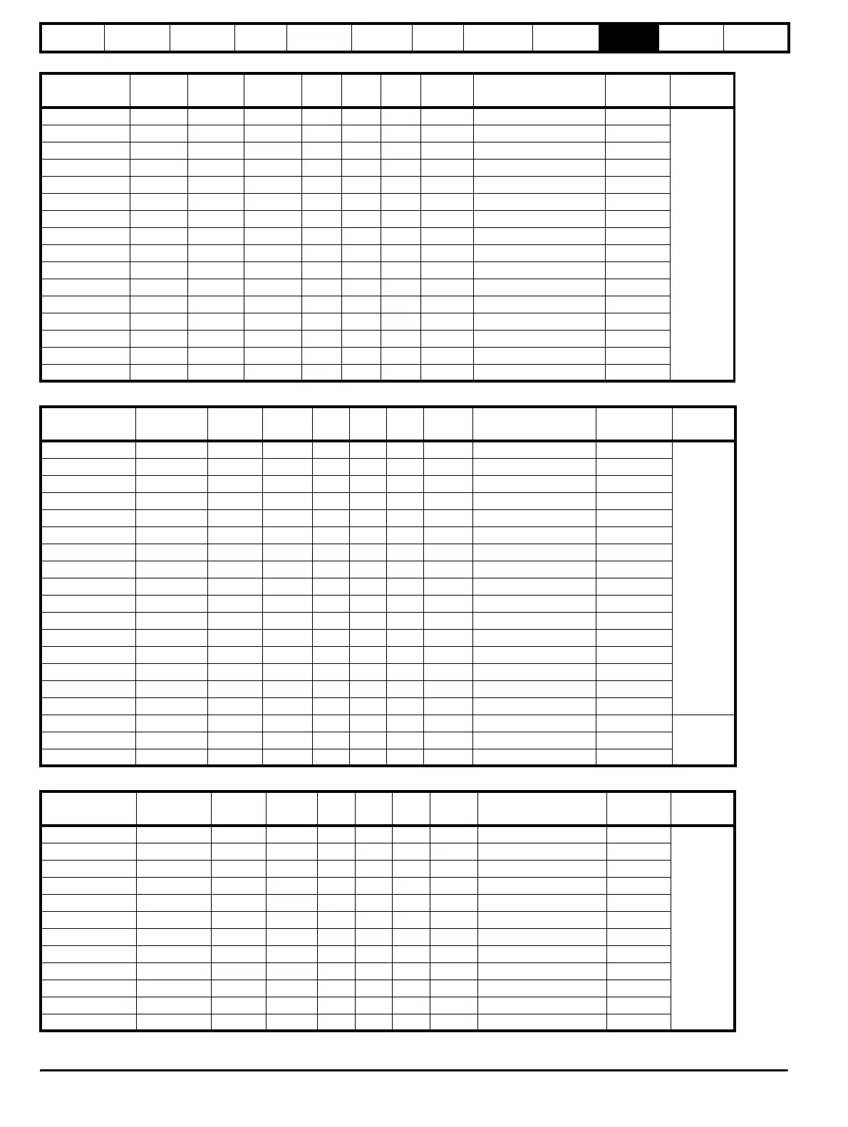
Table 10-26 200V SFF inductor specifications
Table 10-27 400V SFF inductor specifications
Table 10-28 575V / 690V SFF inductor specifications
Inductor part
number
Amps mH
Losses
W
L
mm
D
mm
H
mm
Weight
kg
Fixing centres (x * y)
mm
Fixing
mm
Fixing
type
4401-1310 9.6 0.88 10 150 90 150 4 120 x 47 8 x 18
B
4401-1311 11.0 1.50 18 150 90 150 4 120 x 47 8 x 18
4401-1312 15.5 1.10 26 150 90 150 4 120 x 47 8 x 18
4401-1313 22 0.70 33 150 90 150 4 120 x 47 8 x 18
4401-1314 31 0.50 37 190 100 180 6 130 x 54 8 x 20
4401-1315 42 0.40 38 190 120 180 10 130 x 74 8 x 20
4401-1316 56 0.30 48 190 160 180 12 130 x 184 8 x 20
4401-1317 68 0.25 58 190 160 180 12 130 x 184 8 x 20
4401-1318 80 0.20 60 190 160 180 13 130 x 184 8 x 20
4401-1319 105 0.16 78 255 160 240 16 200 x 180 10 x 20
4401-1320 130 0.13 86 255 170 240 20 200 x 90 10 x 20
4401-1321 156 0.11 92 255 180 240 22 200 x 100 10 x 20
4401-1322 192 0.088 97 255 190 240 25 200 x 100 10 x 20
4401-1323 250 0.068 119 300 180 300 37 204 x 113 10 x 20
4401-1324 312 0.055 170 300 180 300 37 204 x 113 10 x 20
4401-1325 350 0.048 162 300 190 300 49 204 x 123 10 x 20
Inductor part
number
Amps mH
Losses
W
L
mm
D
mm
H
mm
Weight
kg
Fixing centres (x * y)
mm
Fixing
mm
Fixing
type
4401-0162 9.5 3.160 28 150 90 150 4 120 x 47 8 x 18
B
4401-0163 12 2.500 35 150 90 150 4 120 x 47 8 x 18
4401-0164 16 1.875 37 180 100 190 6 120 x 54 8 x 20
4401-0165 25 1.200 40 180 150 190 10 120 x 74 8 x 20
4401-0166 34 0.880 52 180 160 190 12 120 x 84 8 x 20
4401-0167 40 0.750 60 180 160 190 12 120 x 84 8 x 20
4401-0168 46 0.650 60 180 160 190 13 120 x 84 8 x 20
4401-0169 60 0.500 80 240 160 255 16 200 x 80 10 x 20
4401-0170 70 0.390 90 240 170 255 20 200 x 90 10 x 20
4401-0171 96 0.315 100 240 180 255 22 200 x 100 10 x 20
4401-0172 124 0.240 110 240 190 255 25 200 x 100 10 x 20
4401-0173 156 0.190 130 300 180 300 37 204 x 113 10 x 20
4401-0174 180 0.165 170 300 180 300 37 204 x 113 10 x 20
4401-0175 220 0.135 180 300 190 300 49 204 x 123 10 x 20
4401-0176 300 0.100 220 300 200 300 50 204 x 130 10 x 20
4401-1205 350 0.08
4401-0176 600 0.050 400 410 300 430 110 280 x 260 11
A4401-0176 900 0.034 530 480 320 500 140 320 x 240 11
4401-0176 1200 0.025 700 480 320 560 170 320 x 240 11
Inductor part
number
Amps mH
Losses
W
L
mm
D
mm
H
mm
Weight
kg
Fixing centres (x * y)
mm
Fixing
mm
Fixing
type
4401-1211 22 1.40 36 190 120 180 10 130 x 74 8 x 20
B
4401-1213 36 1.40 81 255 160 240 16 200 x 80 10 x 20
4401-1214 43 1.20 86 255 170 240 20 200 x 90 10 x 20
4401-1215 52 1.00 93 255 180 240 22 200 x 100 10 x 20
4401-1216
63 0.80 95 255 190 240 25 200 x 100 10 x 20
4401-1217 85 0.60 122 300 180 300 37 204 x 113 10 x 20
4401-1218 100 0.50 190 300 180 300 37 204 x 120 4 x 10
4401-1219 125 0.40 172 300 190 300 49 204 x 123 10 x 20
4401-1220 144 0.35 177 300 200 300 50 204 x 130 10 x 20
4401-1221 168 0.30 207 300 200 300 50 204 x 130 10 x 20
4401-1222 192 0.26 220 325 220 325 55 204 x 160 4 x 10
4401-1223 192 0.21 189 300 200 300 50 204 x 130 10 x 20