Safety
Information
Introduction
Product
information
System
design
Mechanical
installation
Electrical
installation
Getting
started
Optimisation Parameters
Tec h nic a l
data
Component
sizing
Diagnostics
Unidrive SP Regen Installation Guide 85
Issue Number: 2 www.controltechniques.com
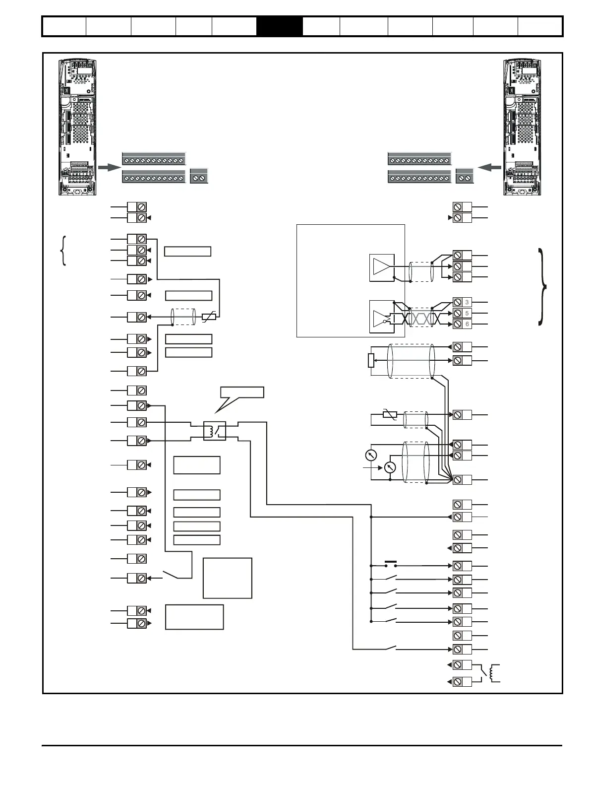
Figure 6-18 Default terminal functions
* Analogue input 3 can be configured as a motor thermistor input, refer
to the Unidrive SP User Guide.
**The Secure Disable / Drive enable terminal is a positive logic input only.
Polarised signal
connectors
1
11
21 31
41
42
0V common
External +24V input
0V common
1
2
5
6
3
21
22
23
24
25
26
27
28
29
30
31
41
42
4
7
11
9
10
8
Analogue input 3
Motoring drive
1
11
Polarised signal
connectors
21 31
41
42
0V common
External +24V input
Analogue frequency/speed
reference 1
Connections for
single-ended input
signal
Connections for
differential input signal
1
2
5
6
3
21
22
23
24
25
26
27
28
29
30
31
41
42
Speed /
frequency
nalogue
frequency/speed
reference 2
4
7
11
9
10
Torque
(active
current)
nalogue input 3
(Motor thermistor*)
Regen drive
Non inverting
Inverting
+10V output
Analogue input 2
Analogue output 1
Analogue output 2
0V common
0V common
+24V output
0V common
Enable motor drive
Contactor closed
Drive healthy
0V common
Secure Disable/
Drive enable**
Status relay
Analogue input 1
0V common
Non inverting
Inverting
0V common
Non inverting
Inverting
+10V output
Analogue input 2
Analogue input 3
Analogue output 1
Analogue output 2
0V common
0V common
+24V output
0V common
At zero speed
Reset
Run forward
Run reverse
Analogue input 1
/ input 2 select
Jog forward
0V common
Secure Disable/
Drive enable**
Status relay -
drive healthy
Enable
connected
through Regen
system
auxiliaries
Used for control
of external regen
system contactors
User definable
User definable
User definable
User definable
User definable
User definable
User definable
Input from
regen circuit
Analogue input
Enable relay
User definable
Optional
Regen inductor
thermistor
8
Reset input