Safety
Information
Introduction
Product
information
System
design
Mechanical
installation
Electrical
installation
Getting
started
Optimisation
Parameters
Techn i cal
data
Component
sizing
Diagnostics
Unidrive SP Regen Installation Guide 95
Issue Number: 2 www.controltechniques.com
Table 9-3 Menu 3 Regen parameter descriptions
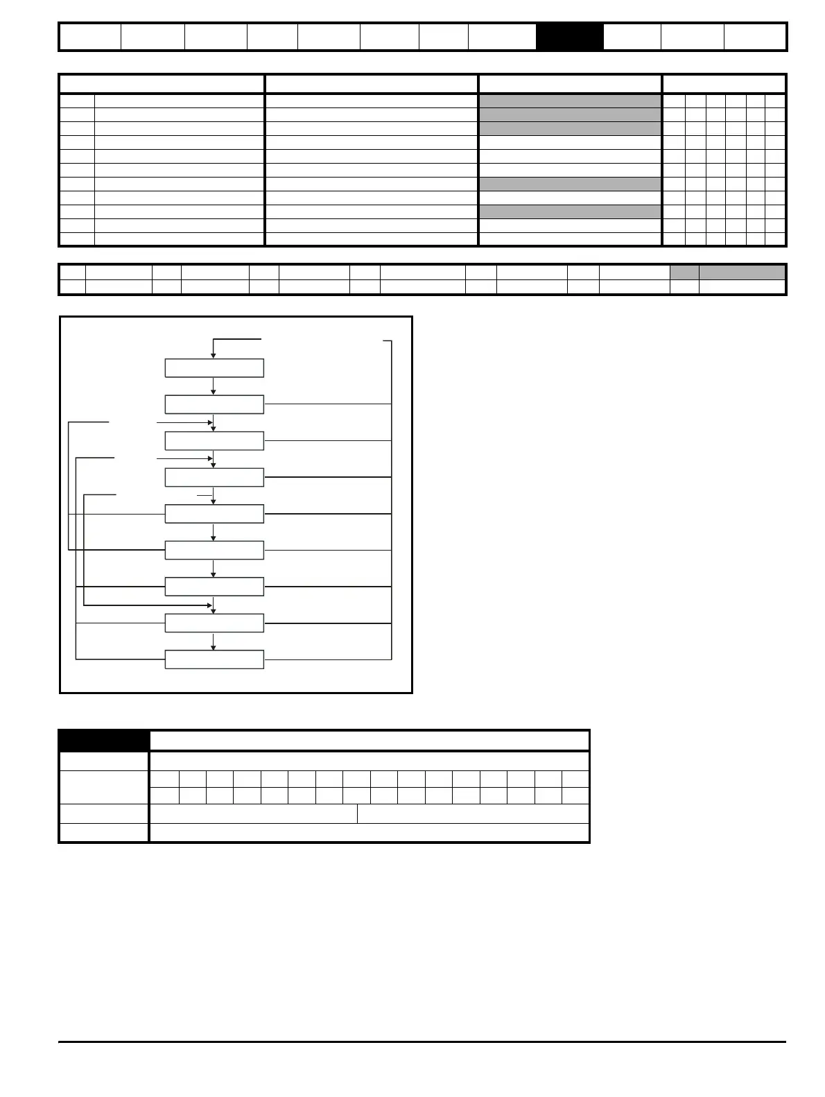
Figure 9-2 Current trimming state diagram
The power (Pr 5.03) and the reactive power are the power or VAR's respectively that flow from the supply to the drive. Therefore when this parameter
is positive the phase current flowing from the supply to the drive contains a component that lags the respective phase voltage, and when this
parameter is negative the phase current contains a component which leads the respective phase voltage at the drive terminals.
Parameter
Range(
Ú) Default(Ö)
Type
3.01 Reactive power ±POWER_MAX kVAR’s RO Bi FI NC PT
3.02 Input inductance 0.000 to 500.000 mH RO Uni NC PT
3.03 Regen drive status 0 to 15 RO Uni NC PT
3.04 Regen restart mode 0 to 2 1 RW Uni US
3.05 Voltage setpoint 0 to DC_VOLTAGE_SET_MAX V 700 Vdc RW Uni US
3.06 Voltage controller Kp gain 0 to 65535 4000 RW Bi US
3.07 Close start up contactor OFF (0) or On (1) RO Uni NC
3.08 Main contactor closed OFF (0) or On (1) 0 RO Uni NC
3.09 Enable motor drive OFF (0) or On (1) RO Uni NC
3.10 Power feed forward compensation ±100.0 % 0.0 RW Bi NC
3.11 Current trimming mode 0 to 1 0 RW Uni US
RW Read / Write RO Read only Uni Unipolar Bi Bi-polar Bit Bit parameter Txt Text string
FI Filtered DE Destination NC Not cloned RA Rating dependent PT Protected US User save PS Power down save
3.01
Reactive power
Drive mode Regen
Coding
Bit SP FI DE Txt VM DP ND RA NC NV PT US RW BU PS
1 12111
Range Regen ±POWER_MAX kVAR’s
Update rate Background
Mains Loss
Current Trim
Close Main Contactor
Waiting for Enable
Open Contactor
Current Trim
Close Main Contactor
Active
(not synchronised)
Synchronied
Disabled
Disabled
Enabled Pr
3
.
11
=0
Synchronised
Contactor closed + 100ms delay
Trim complete
Contactor open + 100ms delay
Enabled (Pr
3
.
11
=1)
Contactor closed + 100ms delay
Trim complete
Supply o.k
Mains loss or contactor open
when it should be closed