Interconnecting condenser
blower harness
Field-supplied 24V
(NEC Class 2 wiring)
to condensing module
(if applicable).
Field-supplied, field wired
thermostat wire to remote
wall box
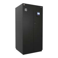
Entrance for Customer
Low-Voltage Connections
Fan Speed Control captube
passage holes
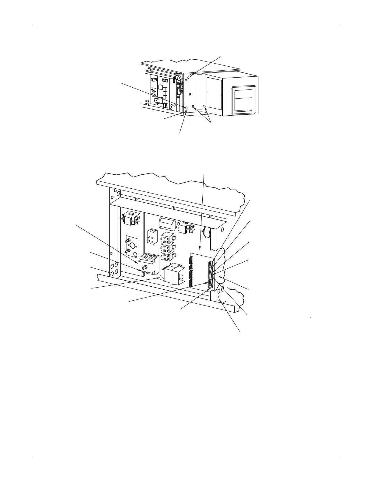
Remote Humidifier Contact
Field-supplied 24V Class 2
wiring to Terminals 11 and 12,
located in field wire
compartment
Heat Rejection Connection.
Field-supplied 24V NEC Class 2 wiring.
See note 2. For remote air-cooled
units from Terminals TB2-1, 2, 3 and 4
in the Fan/Coil module to Wires 1, 2,
3 and 4 in the condensing module:
1. 24V GND
2. 24V Supply
3. High Pressure Alarm (OPT)
4. Hot Gas Bypass Connection
(Optional) Condensate Pump Auxiliary
Float Switch Connection to Terminal
TB1-8 and TB1-9.
Common Alarm Connection
Field-supplied 24V Class 2 wiring to
common alarm Terminal TB1-6 and
TB1-7
Remote Unit Shutdown. Replace existing
jumper between Terminals TB1-4 and TB1-5
with normally closed switch having a
minimum 75VA rating, use field-supplied
24V Class 1 Wire
Drycooler/Circulating pump
control circuit TB70-71. Optional
w/Econ-O-Cycle models. Use
field-supplied 24V Class 2 wire.
Customer Remote Alarm Connection
Field-supplied 24V Class 2 wiring to
Terminals TB1-1, TB1-2 and TB1-3.
Entrance for customer
low-volt connection
Site Monitoring Connection. Terminals
TB4-1 (+) & TB4-2 (-) are for connection
of a 2 wire, twisted pair, communication
cable (available from Emerson or others)
to optional Liebert SiteScan
NOTES:
1. Refer to specification sheet for full load amp and wire size amp ratings.
2. Control voltage wiring must be a minimum of 16 GA (1.3mm) for up
to 75'(23m) or not to exceed 1 volt drop in control line.
Remote Control Wall Box Connection
to TB3-1,2,3, 4 connected with field-supplied
thermostat wire (22ga, shielded/jacketed.
Unit control board terminals marked GND,
+5V, T-, T+ must be connected to
corresponding terminals on remote
control wall box.
Earth Ground Connection
Connection terminal for field-
supplied earth grounding wire
Entrance for Customer
High-Volt Connection
High-Volt Power Connections.
Electric service connection
terminals.
Factory-installed disconnect
switch (optional)
DPN000175
Rev. 1
RIGHT
END
 Loading...