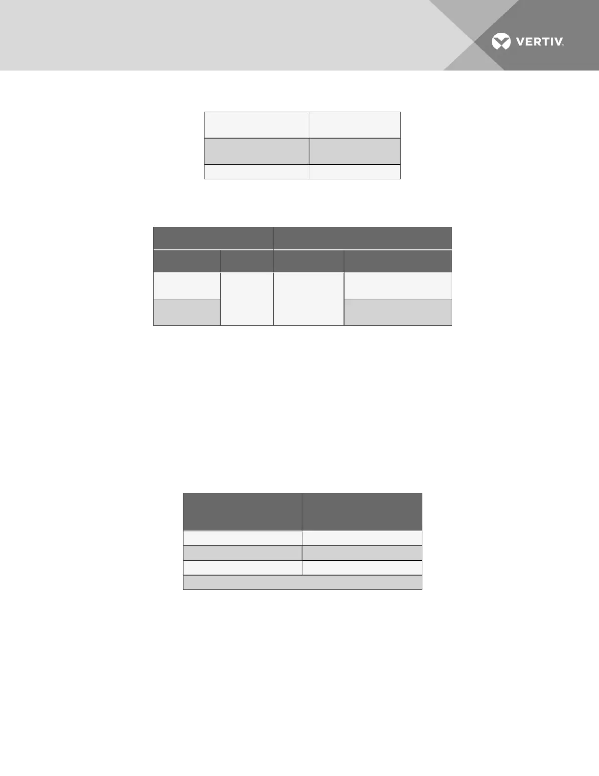
Suction
53 - 95 PSIG
(365 to 655 kPa)
Discharge
(At Design Ambient)
280 psig (1930 kPa)
High-Pressure Cutout 400 psig (2760 kPa)
Table 2.13 Design refrigerant pressures
Input voltage Dry Bulb Air Temperature at Condenser
Minimum Maximum Minimum Maximum
-10%
+10% -30°F (-34°C)
115°F (46°C) Std
Ambient & Quiet-Line
-5% 208/230V
single-phase
125°F (52°C)
High Ambient Models
Table 2.14 Application limits
2.6.1 Low-Voltage Control Wire Connections
Field-supplied four-wire control connection (10-wire on 8-ton units) is required between the outdoor
condensing unit and the evaporator. Refer to Figure 2.5 on page8 ,Figure 2.7 on page10Figure 2.8 on
page11 and electrical schematic (Figure 2.9 on page12 throughFigure 2.10 on page13).
2.6.2 Low-Voltage Control Wire Sizing
Low-voltage wiring should be sized to allow a 1 volt maximum drop due to line resistance between the
evaporator and condensing unit. Use NEC Class 1 or 2 wiring according to wire routing conditions chosen,
local codes and application limits in Table 2.14 above and Table 2.15 below.
Max. Distance*
ft. (m)
Min. Wire Gauge
AWG (mm
2
)
50 (15) 20 (0.75)
100 (30) 18 (1.0)
150 (45) 16 (1.5)
* One-way control wire run between outdoor condensing unit and evaporator.
Table 2.15 Recommended minimum wire size
Vertiv | Liebert PFH Installer/User Guide | 23
 Loading...