21
___________________________________RAH / PAH Ka_________________________________
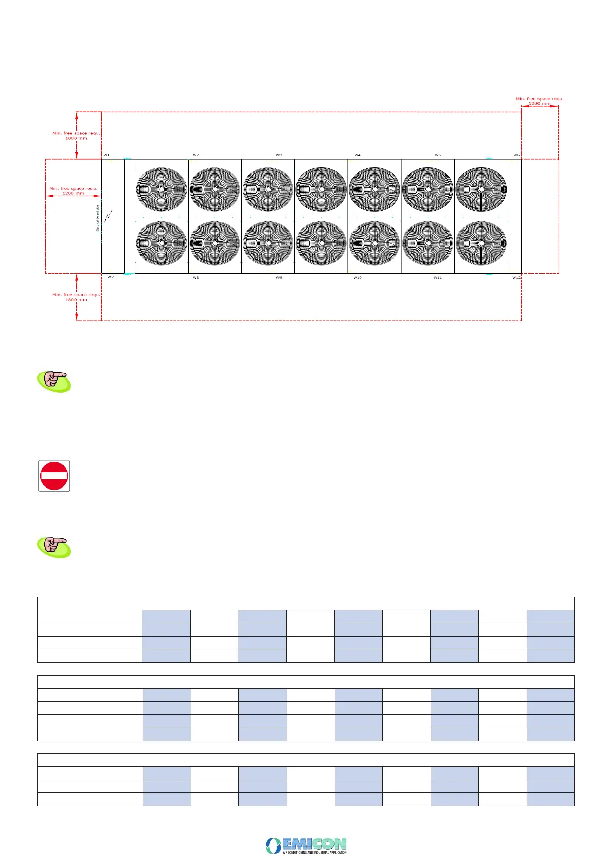
No specic foundations are required for the unit positioning, since it can be just placed on the supporting surface.
SPACES TO BE LEFT FREE
You need to respect the distances shown in the gure also for possible side hydraulic connections.
Before installing the unit, verify that the features of the equipment, reported on the technical documents enclosed in the Handbook, match the design
ones.
3.5 HYDRAULIC CIRCUIT
The unit is designed to be connected to a chilled water distribution system and the pipe laying must be done by expert refrigeration plant technicians.
The uid must be free from aggressive substances or those ones which are not compatible with copper, carbon steel, aluminium and all the other
materials in the system. If any doubt arises, carry on specic uid chemical analyses, sending the result to the Manufacturer, in order to nd and agree
required measures.
The hydraulic system must be sized by a qualied designer and realized by qualied personnel, appointed by the Owner, in compliance with current local regulations.
The hydraulic connections diameters are shown in the here below table as well as on the dimensional drawing attached to the Handbook. The
diameter of the hydraulic system pipes must be chosen in order to keep the pressure drops in the circuit inside acceptable limits.nel circuito.
3.5.1 WATER CONNECTIONS DIAMETER
CHILLER RAH Ka
MODEL 361 431 Ka K361 521 Ka 602 Ka 702 Ka 802 Ka 922 Ka 1032 Ka 1102 Ka 1202 Ka
CHILLER RAH S Ka
MODEL 361 431 S Ka 361 521 S Ka 602 S Ka 702 S Ka 802 S Ka 922 S Ka 1032 S Ka 1102 S Ka 1202 S Ka
HEAT PUMP PAH Ka
MODELL 361 431 Ka K361 521 Ka 602 Ka 702 Ka 802 Ka 922 Ka 1032 Ka 1102 Ka 1202 Ka