31
___________________________________RAH / PAH Ka_________________________________
3.7 ELECTRICAL CONNECTIONS
The electrical power supply must be sized by a qualied designer and realized by qualied technicians, on behalf of the Owner, in compliance with current local
regulations.
The supply cable upstream the unit must be protected by an automatic switch with suitable size and features and in compliance with current local dispositions.
The system must be realized in order to permit the unit power cutting, without stopping other services like lightening, ventilation, alarms and safety systems.
Any intervention on the electrical circuit must be done by expert and suitable qualied personnel, in compliance with current local laws and regulations.
Before any intervention on the electrical system of the unit, consult the wiring diagram enclosed in the Handbook.
!|”
Verify that Voltage and frequency match the ones on the identication Tag and on the wiring diagram enclosed in the Handbook.
Use a power cable with a suitable cross-section and as short as possible, to avoid excessive voltage drops.
To size the cable cross-section, the size and intervention value of the automatic switch, refer to the wiring diagram enclosed in the Handbook.
3.7.1 CONNECTION TO THE POWER SUPPLY
The unit must be supplied by a 4 pole-cable (3 poles +GND), if the power supply voltage is 400 V /3ph / 50 Hz (+/- 2%) +GND.
On demand, it is possible having special power supplies (check Identication tag and wiring diagram).
Connect the phases to the terminals of the main switch and the earth wire to its own terminal. Use a power cable with a suitable cross-section and as short as
possible, to avoid excessive voltage drops.
Protect the power cable upstream the unit through an automatic switch with suitable size and features. The power cable cross-section and the automatic switch size
can be found in the attached electrical components table together with the main switch size.
The position for power cable entry is shown in the dimensional drawing enclosed in the Handbook. The cable entry point of the unit must be suitably protected in
compliance with current local Regulation.
If the cable arrives from the top, run a bend break, as shown in the side picture.
Before any intervention on the electrical system, visually check that the electrical circuits of the unit have not be damaged during the transport. In particular, verify
that all the terminals screws are correctly tightened and that the cable insulation is intact and undamaged.
The phase conductors of the supply cable must be connected to the main switch input free terminals. The grounding conductor will be connected to the relevant
terminal (identied by the abbreviation PE).
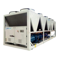
3.7.2 CONNECTION TO THE USER SIDE TERMINAL BOX
A user terminal box with the following pre-arranged free contacts is available:
• General alarm (1).
• Unit remote ON/OFF (2).
Refer to the wiring diagram to verify the exact terminals numbering.