32
___________________________________RAH / PAH Ka_________________________________
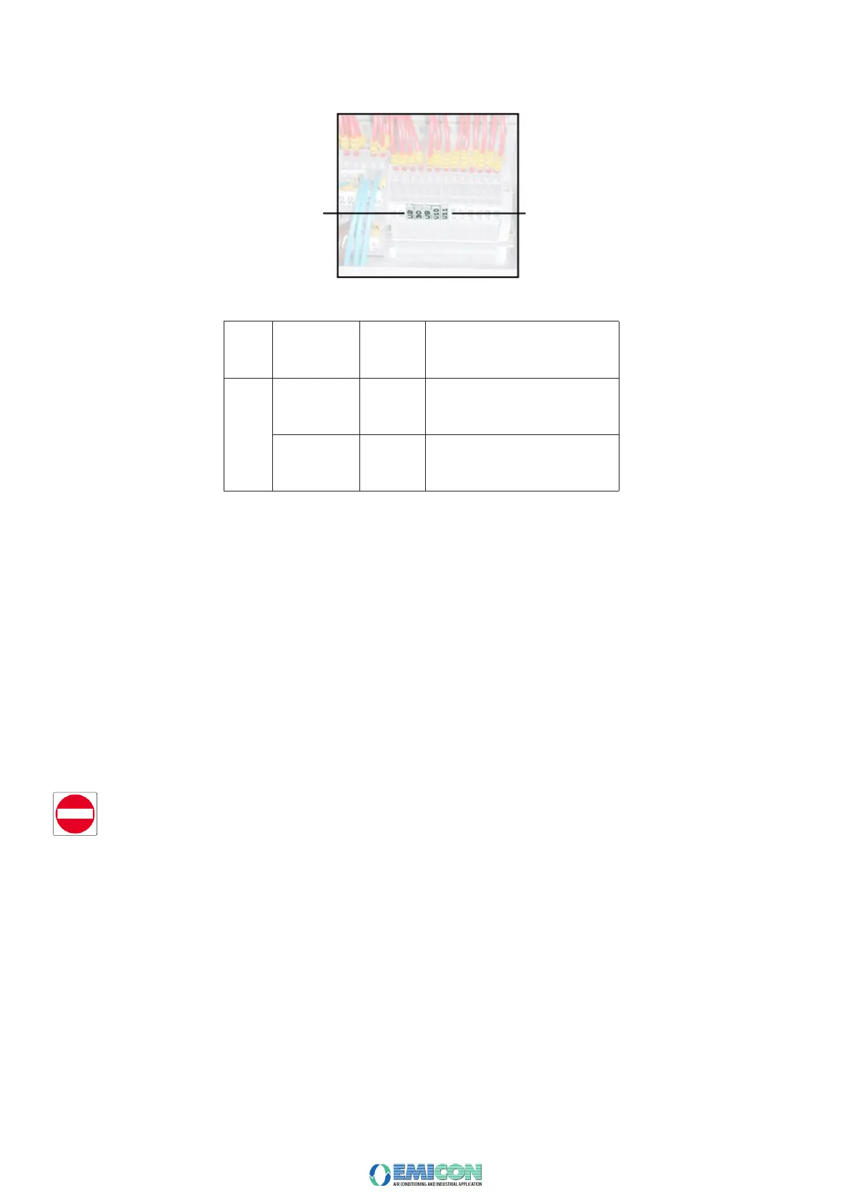
Inside the electrical cabinet there is a terminal box with digital and analogue signals for the unit operation. Since the terminal conguration can be different in each
single unit, refer to the one shown in the wiring diagram enclosed in the Handbook.
As an example, here below the pre-arranged terminals for free contacts described in the table are represented.
Remote ON/OFF
If, once the phase inversion is done, a component rotates in the wrong sense, verify and if required correct the supply cables sequence for each component, as
here above described.
If the water circulation pump is not controlled by the unit microprocessor, it is advisable to connect an auxiliary contact of the pump contactor to the pre-arranged
remote ON/OFF terminal of the electrical cabinet (see attached diagram), so that the unit can start only when pump is working.
3.7.3 SUPPLY-PHASES RIGHT SEQUENCE CHECK
The rotation direction of all electrical motors installed on the unit (fans, pumps), is veried and harmonized during the operational test made by the Manufacturer
(except for those units which cannot be started, like, for example the ones with a special power supply).
Once the connection to the power supply is done, verify that the phases are connected in the right sequence. For this purpose, verify that all the installed motors
rotate in the right direction.
In case of three-phase power supply, if one of the components rotates in the wrong direction, it could be assumed that all the installed motor rotate in the wrong
direction, therefore disconnect 2 supply conductors and invert their position on the main switch input terminals.
To avoid any wrong connection, no further conductor of the main switch must be disconnected except the two involved in the operation.
If once the phases have been inverted, a component still rotates in the wrong direction, verify and if required correct the single component supply conductors
sequence.