16
___________________________________RAH / PAH Ka_________________________________
2.8 WIRING DIAGRAM
The diagram of power and control electrical circuits of the unit, terminals and relevant table which summarizes the features of the used components, is attached to
the Handbook.
2.9 SOUNDLEVELS
The unit can autonomously and automatically work so no operator is required.
It is therefore not required supplying the sound data in the command station; in the technical datasheet it is specied the weighted average value of the sound pressure
level, at 1 m from the unit in free eld, at full load operation.
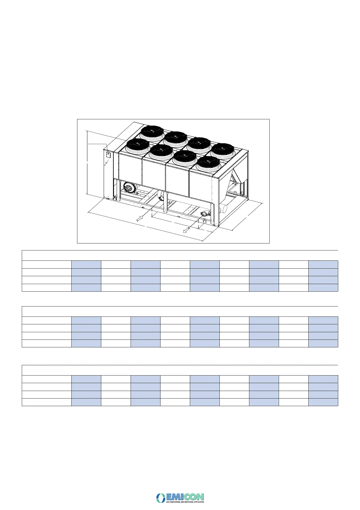
2.10 DIMENSIONAL DRAWING
In the here below table, you can nd the overall dimensions of all the models of RAH/PAH Ka series:
H
L
P
ELECTRICAL CABLE
INLET SECTION
2
In H O
Out H O
2
G
G
X
I
CHILLER RAH Ka
MODEL 361 431 Ka K361 521 Ka 602 Ka 702 Ka 802 Ka 922 Ka 1032 Ka 1102 Ka 1202 Ka
4750 4750 5720 5720 5720
2300 2300 2300 2300 2300 2300 2300 2300 2300
CHILLER RAH S Ka
MODEL 361 431 S Ka K361 522 S Ka 602 S Ka 702 S Ka 802 S Ka 922 S Ka 1032 S Ka 1102 S Ka 1202 S Ka
4750 4750 5720 5720
2300 2300 2300 2300 2300 2300 2300 2300 2300
HEAT PUMP PAH Ka
MODEL 361 431 Ka K361 521 Ka 602 Ka 702 Ka 802 Ka 922 Ka 1032 Ka 1102 Ka 1202 Ka
4750 4750 5720 5720
2300 2300 2300 2300 2300 2300 2300 2300 2300