22
___________________________________RAH / PAH Ka_________________________________
Follow the here below listed general instruction in order to realize the cooling circuit:
- The piping path must be done so to limit as much as possible the pressure drops in the system.
- The pipes must be suitably supported by brackets and laid so to allow an easy inspection and maintenance.
- The material used to realize the system must have a nominal pressure not lower than PN6.
- During piping installation, all required measures to avoid dirt and solid particles enter the tubes must be taken.
- The water circulation pump must be able to give the appropriate water ow capacity with required available pressure to overcome the system pressure
drops in any predictable working condition.
- The hydraulic circuit must work with a pressure between 1,5 and 6 bar. To this purpose one or more diaphragm expansion vessels are required, with
suitable volume and pre-charge pressure.
If the hydraulic circuit is designed to work with pressures lower than 1,5 bar (open systems for example) or higher than 6 bar, you need to inform the Manufacturer
to agree the measures to apply:
• The system must be protected by a suitably sized safety valve with a calibration pressure not higher than 6 bar.
• Along the circuit and especially in the upper points, air vent valves must be installed.
• The system must have, in the most suitable position, drainage connections.
• The system must have connections for lling it with water and, if required, for adding antifreeze substances.
• Once the circuit is nished, it must be washed with suitable substances, in order to avoid that dirt and foreign particles can remain inside it causing miss
functioning and damages during operation.
• To connect the unit to the water distribution network, use the prearranged sections shown in the attached dimensional drawing.
During leak detection, the system must be subjected to a pressure not higher than 6 bar
3.5.2 CONNECTION TO THE HYDRAULIC SYSTEM
The connection of the unit to the hydraulic circuit must be done by qualied personnel, in compliance with the current local regulations.
The connection of the unit to the system must be done so that the uid to be cooled circulates inside the evaporator in the right direction.
To this purpose, pipes must be connected respecting the indication near the pre-arranged connections of the unit.
For connecting the pipes to the evaporator, it is advisable to follow the instructions here below listed:
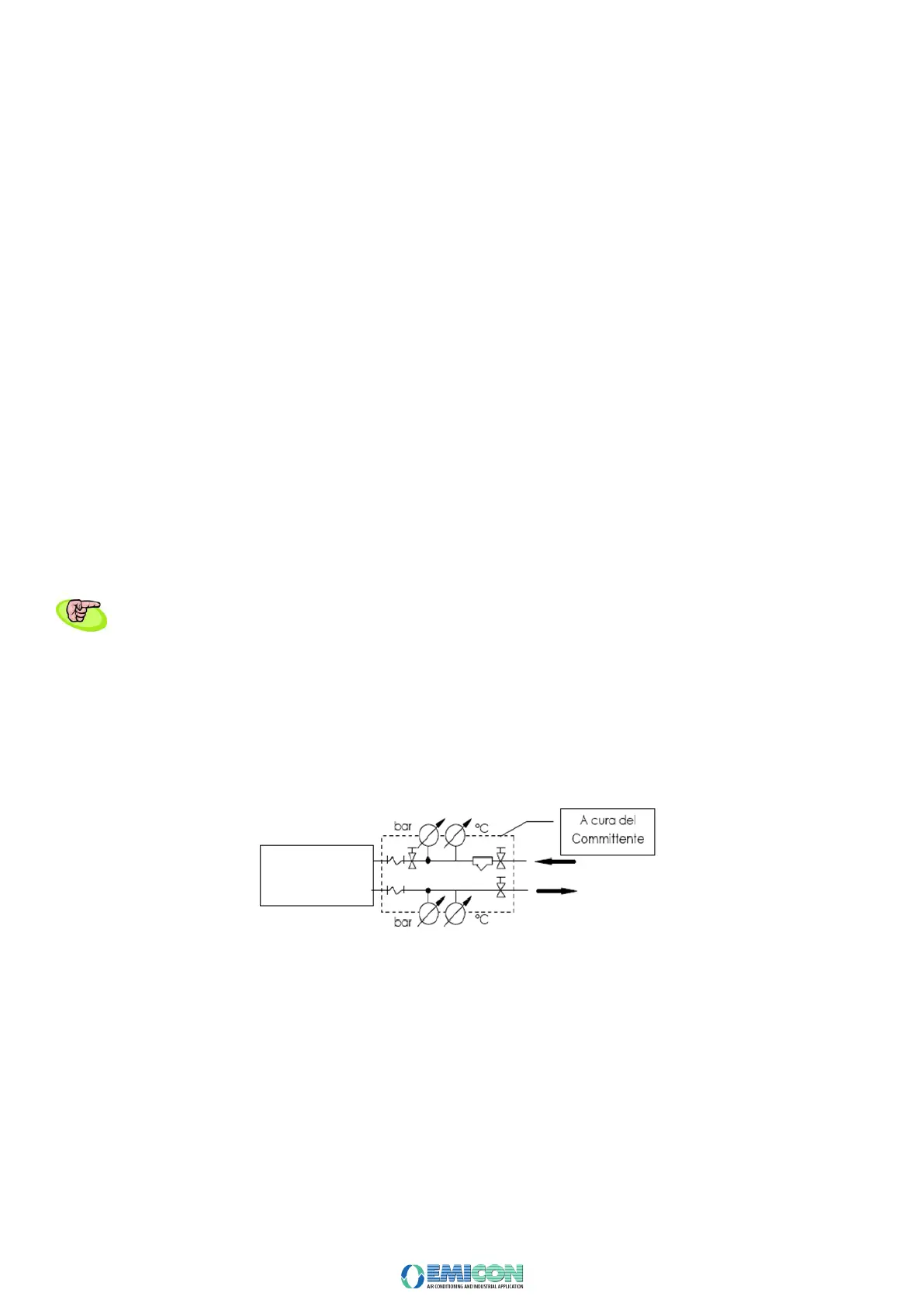
• Connect the pipes as shown in the following diagram
(at customer’s charge)
• Install anti-vibration pipe ttings to avoid any vibration transmission and allow the thermal expansion.
• To avoid the entry of foreign bodies and dirt, install on the unit water inlet a cleanable mechanical lter with grid not larger than 2 mm and with suitable
nominal diameter to reduce pressure drops;
• It is advisable to install shut off valves up and downstream the lter, to make the required cleaning operations easier and faster.
• The installation of probes and gauges near the unit in-and-outlet connections, makes the check of the right unit operation easier;
• The chilled water system must be covered by close cells anti condensation material, thermally insulated, steam resistant and with a thickness suitable to
the worst foreseeable conditions, during working and stops.
• To connect the unit to the hydraulic system, the prearranged connections shown in the dimensional drawing enclosed in the Handbook, must be used.
• Once the circuit is done and the unit installed, an hydraulic leak test of the all system must be done, in order to nd any possible leakage and repair it,
before the unit is lled and commissioned.