9
___________________________________RAH / PAH Ka_________________________________
ELECTRICAL BOARD
The electrical cabinet of the unit, is realized in compliance with current European Standards inside a metal compartment with protection degree IP54 suitable for
external installation and separated from airow.
The main features are:
- Three-phase power supply 400 V/ 3ph / 50 Hz on all the models(if not differently required);
- Low voltage auxiliary circuit 24Vac with insulation transformer;
- Lockable mechanical main switch;
- Protection automatic switches;
- Terminal box for signal and management free-contacts;
The opening panel of the a.m. electrical cabinet is equipped with main switch. Inside the compartment the following main components are also installed:
• Contactors;
• Automatic overload protection switches;
• Transformers;
• Numbered wires;
• Low voltage auxiliary circuit;
• Terminals;
• Management and control electronic cards.
All the unit are subject to a safety cycle with continuity tests on the protection circuit, insulation resistance and tension test (dielectric strength).
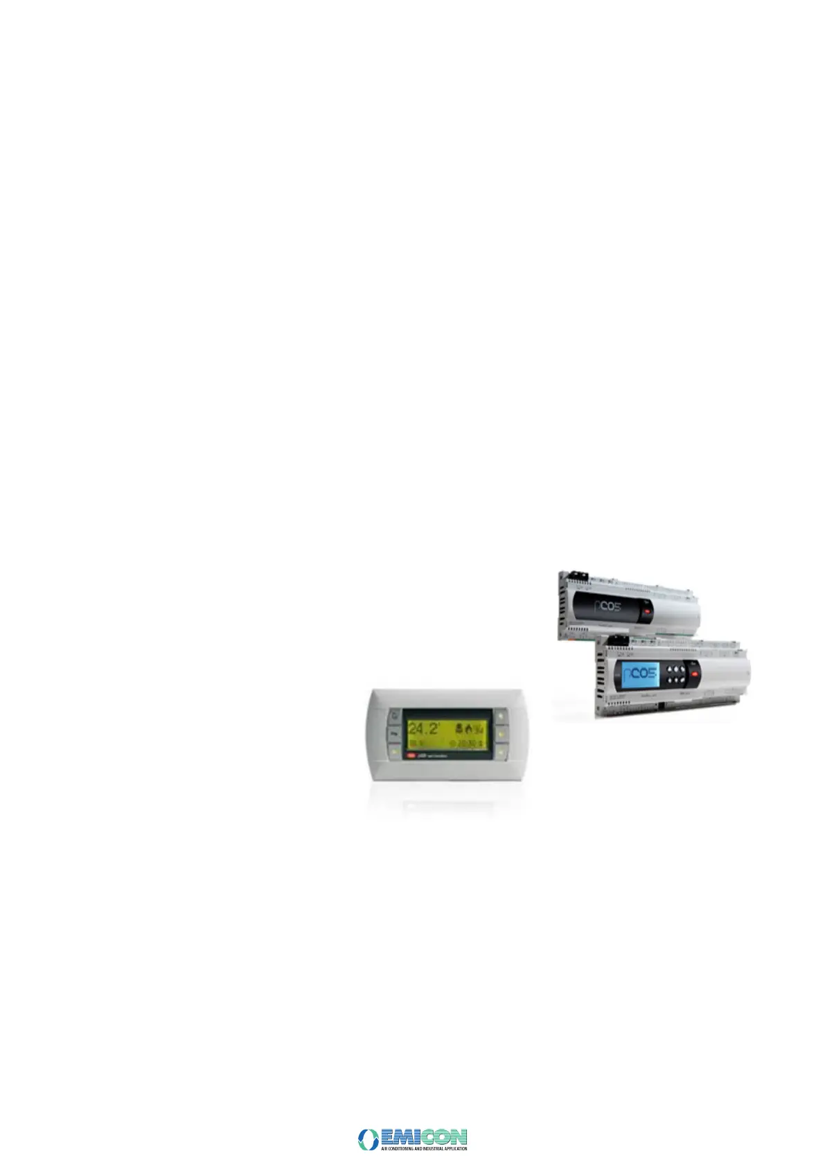
The unit management is realized by the management program uploaded in the electronic microprocessor.
The microprocessor is made up of:
A management control board with terminals for working parameters transmission and control devices activation;
A user interface board with programming buttons and graphic display to show working status and alarms;
The control electronic board manages all the devices installed in the unit on the values of the operation variables, with, inter alia, the following main functions:
• Unit ON/OFF from board or from remote position;
• Management and storage of alert and alarm statuses.
The user interface display of the microprocessor allows, inter alia, to see the following information:
• Working parameters set values,
• Functional variables values;
• Analogue and digital inputs and outputs status;
• Unit operation status;
• Alert and alarm indications;
Possibility to interface EMS/BMS management systems.