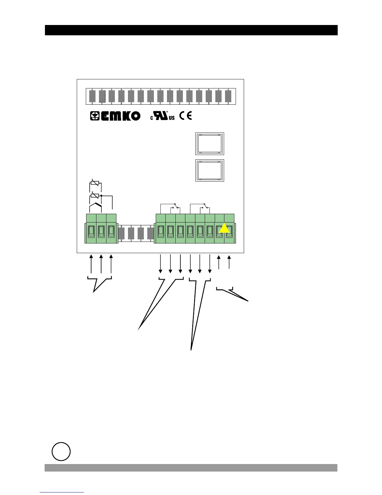
3.2 Electrical Wiring Diagram
Electrical wiring of the device must be the same as ‘Electrical Wiring Diagram’
below to prevent damage to the process being controlled and personnel
injury.
c
Temperature input is in CAT II class.
ii
13
Temperature Input
10
aa
CAT II
P/N : ESM-9910
Y
c
1 2 3 11
(TC, PT-100, PTC or NTC)
Relay Output
This Relay Module is in
ESM-9910.A.BC.0.1/01.00
types
Relay Output
This Relay Module is in
ESM-9910.A.BC.0.1/01.00 and
ESM-9910.A.BC.0.1/00.00
types
C
7A@250VV
OUTPUT-1
NCNOC
7A@250VV
OUTPUT-2
NCNO
4 5 6 7 8 9
TC
+
ı
PTC, NTC
PT 100
Supply Voltage Input
230 V V (±%15) 50/60 Hz - 3 VA
115 V V (±%15) 50/60 Hz - 3 VA
24 V V (±%15) 50/60 Hz - 3 VA
24 V W ( - %15, + %10 ) 50/60 Hz - 3 VA
(It must be determined in order)
L
(+)
N
(-)