- 115 -
Chapter 6. Connection
Chapter 6. Connection
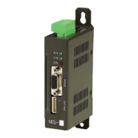
6.1 MCU-X
1) Power connector
- Plug: BR-500LH-2P/ Bee-Ryong Electronics Co., Ltd. (P: Power, I: Input, O: Output)
Note) For input current consumption, refer to Section 1.5 General Specification.
2) RS232C/RS485 communication connector
- Plug: HDEB-9P/HIROSE (P: Power, I: Input, O: Output)
Note)
a) During communication wiring, do not connect the case F.G of this product with GND.
b) When using RS485, use a Twist-Pair Shield Cable for signal lines(No.7, 8 pin).
In addition, if this product is an end of RS485 communication terminals, connect the
termination resistor of 120 ~ 220Ω with both ends(No.7, 8 pin) of communication lines.
c) The No.4 pin is for maintaining or repairing the system, so do not connect it with
other signals.
3) Built-in I/O Connector
- Plug: 5264-5/MOLEX (P: Power, I: Input, O: Output)
Note)
a) The common terminal for built-in input contacts is wired internally to the 24V input
power.
b) The common terminal for built-in output contacts is wired internally to the ground of
24V input power.
Pin arrangement Pin No. I/O Signal name Content
1 P/I 24V GND
24V input power ground
2 P/I 24V
24V input power
Pin arrangement Pin No. I/O Signal name Content
1 I PROTOCOL
PROTOCOL selection
Connection to the No.5 pin when using
the PLC communication as RS232C
2 I RxD
RS232C reception data
3 O TxD
RS232C transmission data
4 I Reserved
Used for system maintenance/repairs
(reserved)
5 P/O GND
RS232C Signal Ground
6 P/O 24V
External Teach-Pendant 24V power
7 I/O TRxD +
RS485 transmission/reception data +
8 I/O TRxD -
RS485 transmission/reception data -
9 P/O 24V GND
24V Ground
Pin arrangement Pin No. I/O Signal name Content
1 I INPUT0
Built-in input 0 (XP2: X1.4, XA2: X0.E)
2 I INPUT1 Built-in input 0 (XP2: X1.5, XA2: X0.F)
3 O OUTPUT0 Built-in output 0 (XP2: Y0.A, XA2: Y0.8)
4 O OUTPUT1 Built-in output 1 (XP2: Y0.B, XA2: Y0.9)
5 O OUTPUT2 Built-in output 2 (XP2: Y0.C, XA2: Y0.A)
6
7
8
9
1
2
3
4
5