Do you have a question about the Emotiontek MCU 2 Axis and is the answer not in the manual?
General safety warnings for severe consequences such as personal injury or death.
Safety warnings for serious or slight personal injury or physical damage.
Safety precautions for equipment operation in unplanned events like power outages.
Precautions for product use in general environments and avoiding damage.
Safety warnings before installation and wiring to prevent shock or damage.
Precautions for electrical grounding and line separation during wiring.
Safety warnings during startup and maintenance to prevent shock or fire.
Precautions for detachment/attachment and general product handling.
Guidelines for treating the product as industrial waste.
Guidelines for product placement and environmental considerations.
Recommendations for input power supply, noise measures, and line separation.
Procedures for applying dedicated type-3 earth grounding.
Description of MCU usage based on slave board combination.
Key characteristics including size, ease of use, and functions.
Industries and applications where the MCU is utilized.
Explanation of the product naming convention.
Detailed technical specifications for various MCU models.
Recommended environmental conditions for product operation and storage.
Important safety and installation guidelines to prevent damage or malfunction.
Categorization of commands, variables, and contacts used in MC programming.
Detailed descriptions and examples of MC program commands.
Explanation of P, F, D(E), and L variable types for MC programs.
Definition and purpose of homing in machine operation.
Configuration parameters for homing signals, direction, and methods.
Detailed methods for executing homing return based on controller type.
Practical examples illustrating homing return procedures.
List and description of fundamental PLC commands.
Commands linking PLC contacts with motion control functions.
Detailed explanations of PLC basic command functions.
Definitions and examples of PLC application commands.
Detailed descriptions of PLC commands for motion control.
Overview and list of basic system parameters.
Detailed explanations of individual system parameters and their functions.
Connector pin assignments and wiring details for MCU-X.
Connector pin assignments and wiring details for MCU-A2.
Connector pin assignments and wiring details for MCU-P2.
Connector pin assignments and wiring details for MCU-L.
Connector pin assignments and wiring details for MCU-E.
Electrical wiring diagrams for system connections.
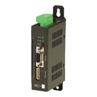
Dimensional drawings and connector information for external appearance.
Software interface for PC-based MCU operation and control.
Functions within the Tool menu for system monitoring and control.
Setting and managing basic operational parameters.
Parameters for extending MCU functionality.
Configuration settings for PLC communication interfaces.
Comprehensive list of system alarms, messages, and countermeasures.
Mapping of MC output signals to PLC signals.
Mapping of PLC input signals to MC input signals.
Practical examples of MC flags for automatic operation control.
Examples of MC flags for manual operation control.
Memory map detailing input, output, and flag contacts for MCU-XA2.
Memory map for PLC communication interface parameters.
Interface details for connecting MCU-XA2 with various servo drives.
| Brand | Emotiontek |
|---|---|
| Model | MCU 2 Axis |
| Category | Controller |
| Language | English |