PWM Variable Speed Control
© 2019 EMP, Inc. 10
PWM Variable Speed Control
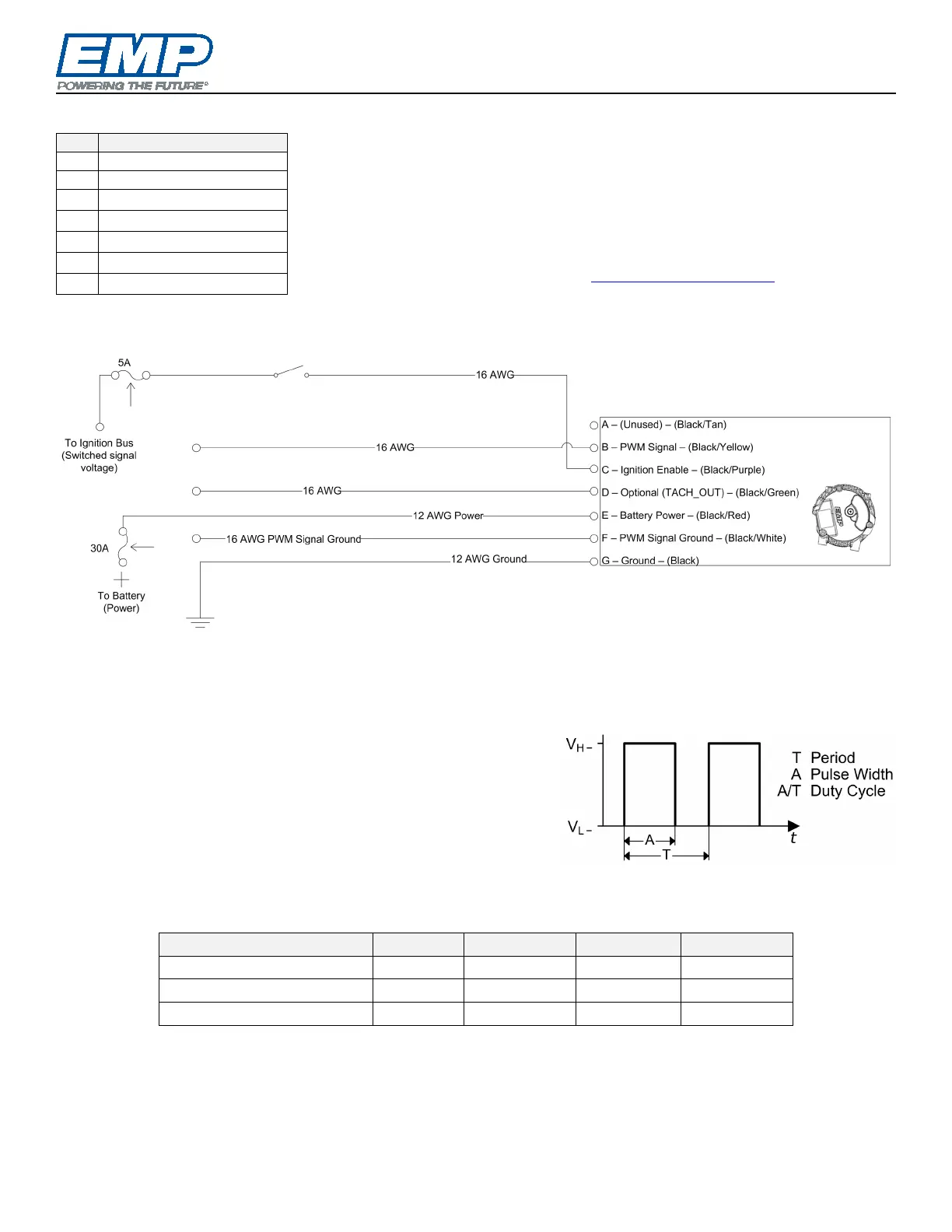
NOTE: All cavities in the mating connector(s) must either be terminated
or plugged to prevent moisture from entering the component.
NOTE: 10 AWG wire can be used for power and ground. Use Delphi 480
cable seal #15324990.
NOTE: For assistance with component calibrations and settings, please
contact EMP Technical Service at service@emp-corp.com
and provide a
serial number for the part in question.
Example PWM Application Schematic
Operation
NOTE: Ignition enable must be present to activate the component. The component will not activate if only
the PWM input is present.
In order to control the component speed, a pulse width modulation
(PWM) signal can be used. A change in the duty cycle of this
signal will result in a corresponding change in component speed.
See the figures on the next page for the relationship between
PWM duty cycle and component speed.
Pulse Width Modulation
The PWM input is compatible with low side drive devices (open/ground).
PWM Input Parameters
V
H
3.0 5 32 V
V
L
-2.0 0 1.0 V
Frequency 100 1000 1500 Hz
NOTE: The PWM input frequency is set in the controller calibration. The controller software will not
automatically adjust or detect input frequency.
The duty cycle range between 10% and 90% is used to linearly interpolate the component speed between the
preprogrammed minimum and maximum speeds (See the next page for EMP pump and fan PWM input control
details). There is a 2% hysteresis for the “ON” set-point. For example, the component will turn on at 10% and