Temperature Input Control
© 2019 EMP, Inc. 13
Temperature Input Control
NOTE: All cavities in the mating connector(s) must either be terminated
or plugged to prevent moisture from entering the component.
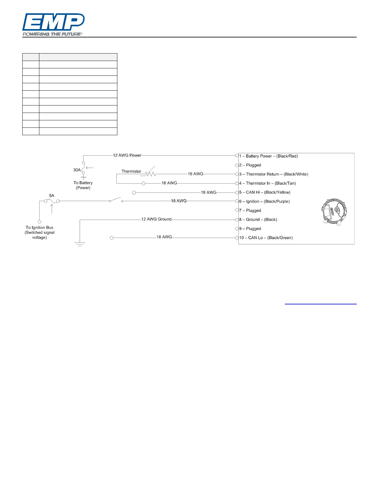
Example Temperature Input Application Schematic
Operation
The temperature input version of the component must be used in conjunction with EMP thermistor part numbers
3130029004 or 3150010016 for liquids or 3150022024 for air. It is possible to use other sensors but special
calibrations will need to be developed to ensure accurate temperature measurements. The thermistor must be
connected across the thermistor input pins (Reference the Example Temperature Input Application Schematics).
The speed vs temperature calibration will be programmed into the component. Contact service@emp-corp.com
with the serial number of your component for details.
EMP harness 3170106122 routes the temperature input pins on the component connector to an EMP thermistor
connector. The remaining pins are routed to a 10-way connector matching the component connector.
These components cannot have CAN addresses configured via harness address resistors.