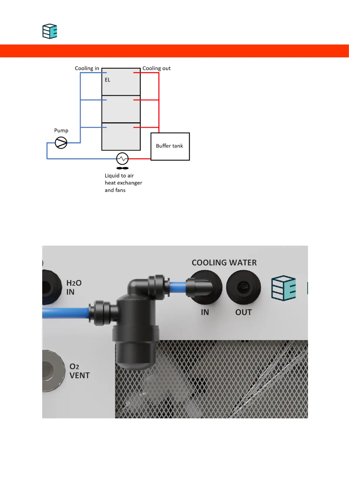
Enapter recommends to set up the
cooling loop according to the schematic
on the left. The return line should be
connected to a non-pressurised buffer
tank. This reduces back-pressure stresses
on the valve inside the device and will
prolong its lifetime. In case the waste heat
of the device will be used, a heat
exchanger for this purpose can be
integrated into this buffer tank. Connect
the pump downstream of the external
heat exchanger. When positioning it at a
lower part of the cooling circuit, gravity
can be used to feed the pump with water.
The cooling agent must be compatible
with 1.4301 stainless steel and LLDPE, free of particles and be usable at up to 60°C. Depending on the
ambient temperature, a frost protection agent may need to be added. To further increase device
reliability, install the filter supplied by Enapter on the cooling line inlet of the device.
EL LC with filter