The external heat exchanger must be sized to be able to transfer up to 1000 W out of each electrolyser
connected to the cooling loop.
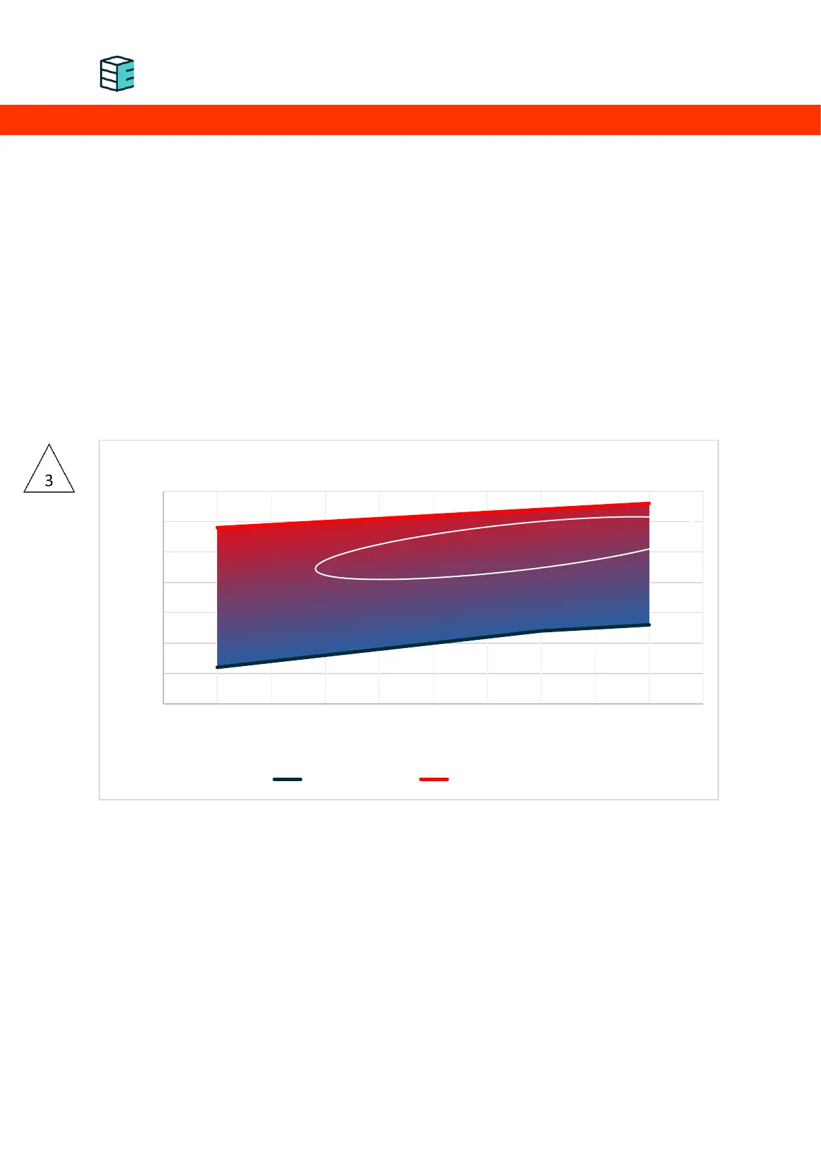
The graph below indicates the operating range of the cooling circuit in terms of allowable inlet
temperature of the cooling agent depending on its flow rate. The flow rates shown refer to the instant
flow rate per electrolyser. The cooling operation of the devices is intermittent so the average flow rate
will be lower. Keep in mind that these values are based on water. When using another cooling agent
with a different heat capacity, the required flow rate needs to be adapted accordingly. The pump used
must be suitable for intermittent operation and able to build up pressure against the closed solenoid
valves inside the electrolysers. The pump must be correctly sized to provide the necessary flow rate
against the pressure drop induced by the piping and electrolysers. The maximum flow rate through one
device is limited to 2 L/min by a flow restrictor. The pressure drop inside the device is up to 800 mbar
at 5 L/min. It is the operator’s responsibility to correctly size the liquid-liquid/liquid-air heat exchanger
and cooling agent pump.
Cooling loop operating range by temperature and flow rate
6
8
12
13
29
30
32
33
0
5
10
15
20
25
30
35
1 1,25 1,5 1,75 2
Coolant inlet temperature [
°C]
Flow rate [l/min]
Recommended coolant operation range
min temperature max temperature