3 Operation
3.1 On-site operation
Operating elements Four keys, which allow the lower and upper range-values to be set, are available for
on-site operation. The key functions are listed in the table below.
Display module The local display module (optional) has two display modes:
•
Display in measurement mode: This is shown as standard
•
Display in calibration mode: This is shown after pressing one of the keys +Z, –Z, +S
or –S once. Returns automatically to measurement mode after 2 seconds.
Key functions
+Z increases the lower range-value (zero) by +1 digit *
–Z decreases the lower range-value (zero) by –1 digit *
+S increases the upper range-value (span) by +1 digit *
–S decreases the upper range-value (span) by –1 digit *
Key combinations (Press keys simultaneously)
Keys Function
Calibration
+Z and –Z the acting pressure is taken as lower range-value (4 mA)
+S and –S the acting pressure is taken as upper range-value (20 mA)
Bias pressure
2 times +Z and +S the acting pressure is taken as bias pressure**
1 time +Z and +S the current bias pressure** is shown
2 times –Z and –S the current bias pressure** is deleted
Securing the measuring point by locking/unlocking
+Z and –S Locking the measuring point
–Z and +S Unlocking the measuring point
The procedure for commissioning the measuring point with local operation is described
in Chapter 4.
Table 3.1
Key functions
* Note: Pressing once activates
the display, only by pressing
again does the display begin to
count. When first pressing the
key the values slowly change
and then increase in speed.
** If the display indicates process
pressure zero not as zero after
calibrating lower range-value
(depending on position) you can
correct the display value to zero
by adopting a bias pressure. The
position calibration using a bias
pressure does not affect the
current output.
-0.1...0.3 bar
-0.1...0.3 bar g
-0.1...0.3 bar g
– –
++
ZS
– –
++
ZS
ZS
+Z
-Z
+S
-S
z
➂
➀
➁
➅
➃
➄
Keys for on-site operation
BA187Y27
Display module
➆
Display in
measurement mode
Display in calibration mode
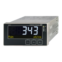
Figure 3.1
User interface of the
Cerabar S, with optional display
module
Display in measurement mode
➀
4-figure display of
measured value and input
parameters
➁
Bar graph of
measured value
➂
Lower range-value (zero)
➃
Upper range-value (span)
➄
Nominal measuring range
With display in
in calibration mode
➅
Display of the calibration point
(Z=Zero, S=Span)
➆
Set measuring range within
the limits of the measuring cell
3 Operation Cerabar S
18 Endress+Hauser

 Loading...