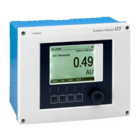
Liquiline CM44P Electrical connection
Endress+Hauser 27
A0039668
25 Connecting the power supply using the
example of the BASE2-E (cabinet device)
* Assignment depends on power supply unit;
make sure it is correctly connected.
85
85
86
86
SD
Display
Sensor supply
+
+
–
Service
PK
GY
PK
GY
1
2
–
+
–
A
B
41
43
42
Alarm
31
31
32
32
0/4 ... 20 mA
+
+
–
–
HART
+
–
A
B
Sensor 2
Ethernet
87
88
97
98
87
88
97
98
BN
WH
GN
YE
BN
WH
GN
YE
Sensor 1
1
2
L/+
N/–
*
Power
L/+
N/–
PE
Power
(internal)
B
A0039624
26 Complete wiring diagram using the
example of the BASE2-E and
external power supply unit (B)
The two device versions may only be operated with the power unit supplied and the
power unit cable. Also pay attention to the information in the operating instructions
supplied for the power unit.
Connecting the supply voltage
1. Route the power supply cable into the housing through the suitable cable entry.
2. Connect the protective ground of the power unit to the threaded bolt specially provided
on the cable mounting rail.
3. Protective ground or grounding provided at the installation location: provide a ground
cable (min. 0.75 mm
2
(corresponding to 18 AWG))
1)
! Guide the ground cable also
through the cable entry and connect it to the threaded bolt on the cable mounting rail.
4. Connect the cable cores L and N (100 to 230 V AC) or + and ‐ (24 V DC) to the plug-in
terminals on the power unit in accordance with the wiring diagram.

 Loading...