EasyManua.ls Logo

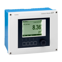
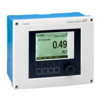
Endress+Hauser Liquiline CM444 User Manual

Endress+Hauser Liquiline CM444
178 pages
To Next Page IconTo Next Page
Page #1 background imageLoading...
Page #1 background image
Products Solutions Services
BA00444C/07/EN/17.13
71238290
Valid as of:
Softwareversion 01.05.00
Operating Instructions
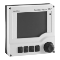
Liquiline
CM442/CM444/CM448
Universal four-wire multichannel controller
Field device

Table of Contents

Other manuals for Endress+Hauser Liquiline CM444

Questions and Answers:

Endress+Hauser Liquiline CM444 Specifications

General IconGeneral
Device TypeController
Measured ParameterspH, ORP, conductivity, oxygen, chlorine, turbidity
OutputsAnalog, digital, relay outputs
Communication ProtocolsPROFIBUS DP, Modbus RS485, Ethernet/IP
DisplayGraphic LCD with backlight
Power Supply100-240 V AC or 24 V DC
Operating Temperature-20 to +60 °C
Protection ClassIP66
Housing MaterialPlastic

Summary

Document Information

Warnings

Explains the structure, signal words, and safety colors of signs according to ANSI Z535.6.

Basic Safety Instructions

Requirements for Personnel

Specifies the qualifications and authorization required for personnel performing installation, commissioning, and maintenance.

Designated Use

Details the intended applications and environments for the Liquiline CM44x controller.

Occupational Safety

Outlines user responsibilities regarding installation instructions and local standards for safe operation.

Installation

Installation Conditions

Specifies the environmental and dimensional requirements for installing the device.

Mounting the Measuring Device

Provides instructions for post mounting the device onto pipes or railings.

Railing Mounting

Details the components and steps for mounting the device on a railing.

Wall Mounting

Details the components and steps for mounting the device on a wall.

Dimensions

Provides the physical dimensions of the field housing in millimeters and inches.

Post Mounting

Details the components and steps for mounting the device on a post.

Post-Installation Check

Lists checks to perform after the device has been installed to ensure proper operation.

Electrical Connection

Connection Conditions

Describes connection requirements for remote operation via HART.

Connecting the Measuring Device

Provides instructions on how to connect the device, including opening the housing.

Connecting the Sensors

Explains how to connect sensors using the Memosens protocol.

Remote Operation via PROFIBUS DP

Explains how to establish remote operation using PROFIBUS DP communication.

Remote Operation via Modbus RS485

Details remote operation setup for Modbus RS485 communication.

Power Supply CM442

Details the power supply connection for the CM442 model.

Power Supply CM444 and CM448

Details the power supply connection for the CM444 and CM448 models.

Connecting Additional Inputs, Outputs or Relays

Provides guidance on connecting additional I/O modules and relays.

Current Outputs

Details the front panel and wiring diagram for current output modules.

Connecting Digital Communication

Explains bus connections on module 485 and lists front panel LEDs.

Hardware Settings

Explains how to set the bus address using DIP switches on module 485.

Post-Connection Check

Lists essential checks after electrical connections are made to ensure safety and correct wiring.

Remote Operation via HART (e.g. via HART modem and FieldCare)

Details the setup for remote operation using a HART modem and FieldCare software.

Remote Operation via Ethernet/Web Server/Modbus TCP/EtherNet/IP

Covers remote operation via Ethernet, Web server, Modbus TCP, and EtherNet/IP.

Sensor Types with Memosens Protocol

Lists sensor types compatible with the Memosens protocol and their connection cables.

Digital Inputs and Outputs

Details the functionality of the DIO module for digital inputs and outputs.

Relays

Shows the front panel and wiring diagrams for relay modules.

Guaranteeing the Degree of Protection

Emphasizes the importance of correct connections for maintaining IP protection and safety.

System Integration

Service Interface

Explains how to connect the device to a computer using the service interface and Fieldcare.

Fieldbuses

Covers communication via HART, PROFIBUS DP, Modbus RS485, and EtherNet/IP.

Operation Options

Access to the Operating Menu via the Local Display

Explains how to navigate and operate the device's menu using the local display.

Locking or Unlocking Operating Keys

Details how to lock and unlock the device's operating keys with or without a password.

Configuration Options

Describes various configuration options like display only and picklists.

Commissioning

Function Check

Outlines safety checks and voltage verification before switching on the unit.

Basic Setup

Guides through making essential basic settings like device tag, date, and time.

Switching on the Unit

Describes the process of switching on the device and initial startup behavior.

Setting the Operating Language

Guides through setting the device's operating language and configuring display settings.

Operation

Display

Details the display interface, soft keys, and measuring modes available on the device.

Current Inputs

Explains how to configure current inputs for limit switches, logbooks, and controller setpoints.

General Settings

Covers general settings such as device tag, temperature unit, output range, and alarm delay.

Loading the Setup

Guides on how to load a previously saved setup configuration onto the device.

Outputs

Details the configuration of current outputs, alarm relays, and optional relays.

Alarm Relay and Optional Relays

Describes the functions that can be output via relays.

Outputting Diagnostics Messages via the Relay

Describes how to output diagnostics messages via the relay.

Firmware Update

Provides instructions on how to install a firmware update using an SD card.

Exporting the Setup

Explains how to export the device configuration in XML format.

Saving the Setup

Explains the advantages and procedure for saving the device setup to an SD card.

Diagnostics and Troubleshooting

General Troubleshooting

Provides steps for troubleshooting issues, including using diagnostic messages and error tables.

Troubleshooting

Guides on identifying and rectifying faults using diagnostic messages.

Maintenance

Calibration

Explains the calibration procedure for sensors, including factory calibration and user-decided intervals.

Cleaning

Provides guidelines for cleaning the controller housing and digital sensors.

Accessories

Sensors

Categorizes and lists various sensors, including glass electrodes, ORP sensors, and pH-ISFET sensors.

Technical Data

Web Server

Details web server features like remote configuration and logbook export.

Input

Specifies measured variables, measuring ranges, input types, and cable specifications.

Digital Inputs, Passive

Details electrical specifications, span, input current, PFM function, and cable for digital inputs.

Output

Describes output signals for HART, PROFIBUS DP, Modbus RS485, Ethernet, and EtherNet/IP.

Current Input, Passive

Covers span, signal characteristic, internal resistance, and testing voltage for current inputs.

Installation and Operation in Hazardous Environment Class I Div. 2

Environment/Properties

Outlines requirements for non-sparking devices in explosive environments, including gas groups and temperature classes.

Control Drawing

Presents a control drawing illustrating the installation and operation in hazardous environments.

Related product manuals