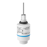
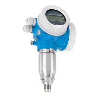
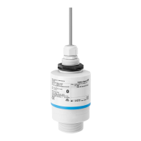
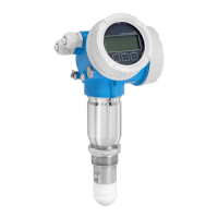
Micropilot FMR20 HART
14 Endress+Hauser
Response time
<3 s
In accordance with DIN EN 61298-2, the step response time is the time following an abrupt
change in the input signal up until the changed output signal has adopted 90% of the steady-
state value for the first time.
Influence of ambient
temperature
The measurements are carried out in accordance with EN 61298-3
• Digital (HART, Bluetooth® wireless technology):
Standard version: average T
C
= ±3 mm (±0.12 in)/10 K
• Analog (current output):
• Zero point (4 mA): average T
K
= 0.02 %/10 K
• Span (20 mA): average T
K
= 0.05 %/10 K
Installation
Installation conditions Installation types
A0030605
10 Wall, ceiling or nozzle installation
A Wall or ceiling mount, adjustable
B Mounted at front thread
C Mounted at rear thread
D Ceiling installation with counter nut (included in delivery)
E Horizontal installation in confined spaces (sewer shaft)
F Shaft wall mounting
Caution!
• The sensor cables are not designed as supporting cables. Do not use them for suspension
purposes.
• Always operate the device in a vertical position in free-space applications.

 Loading...
