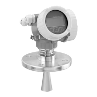
Micropilot FMR51, FMR52 FOUNDATION Fieldbus Installation
Endress+Hauser 25
A0018872
Device A [mm (in)] B [m (ft)] C [mm (in)] H [m (ft)]
FMR51 50(1.97)
> 0.2 (0.7) 50 to 250 (1.97 to 9.84) > 0.3 (1.0)
FMR52 200(7.87)
6.3 Mounting cladded flanges
• Use flange screws according to the number of flange holes.
• Tighten the screws with the required torque (see table).
• Retighten the screws after 24 hours or after the first temperature cycle.
• Depending on process pressure and process temperature check and retighten the
screws at regular intervals.
Usually, the PTFE flange cladding also serves as a seal between the nozzle and the
device flange.
Flange size Number of screws Recommended torque [Nm]
minimum maximum
EN
DN50/PN16 4 45 65
DN80/PN16 8 40 55
DN100/PN16 8 40 60
DN150/PN16 8 75 115
ASME
2"/150lbs 4 40 55
3"/150lbs 4 65 95
4"/150lbs 8 45 70
6"/150lbs 8 85 125

 Loading...


