Wiring Levelflex M FMP40 with PROFIBUS PA
36 Endress + Hauser
4 Wiring
Notes on PROFIBUS PA installation can be found in Operating manual BA198F.
4.1 Quick wiring guide
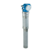
Wiring in F12/F23 housing
L00-FMP41Cxx-04-00-00-en-003
-
-
"
PA - PA +
3 412
PA L
12
3
4
7
Made in Germany
D-79689 Maulburg
Dat./Insp.:
Order Code:
IP68 / NEMA 6P
Ser.-No.:
4-wire
ENDRESS+HAUSER
t >85°C
TA > 70°C:
D01301-A
if modification
see sep. label
X=
Patents
LEVELFLEX-M
90 … 253 V AC 1VA
10,5 … 32VDC 1W
16 … 3 V DC 0,8W
Profibus PA
Foundation Fieldbus
LN= PN=
4 … 20 mA HART 2-wire
1
#
4
5
6
2
3
7
8
E
N
D
R
E
S
S
+
H
A
U
S
E
R
Sealed terminal
compartment
Before connection please note the following:
PROFIBUS devices are marked on the nameplate (1). The
voltage is determined by the PROFIBUS standard and the
desired safety concept. (see chapter 4.3).
Connect potential matching line to transmitter
ground terminal before connecting up the device.
Tighten the locking screw :
It forms the connection between the antenna and the housing
earth potential.
l
l
l
(7)
(8)
When you use the measuring system in hazardous areas, make sure you comply with
national standards and the specifications in the safety instructions (XA’s).
Make sure you use the specific cable gland.
On devices supplied with a certificate, the explosion protection
is designed as follows:
Housing F12 - EEx ia:
Power supply must be intrinsically safe.
The electronics and the current output are galvanically
separated from the probe circuit.
l
l
Connect up the Levelflex M as follows:
Unscrew housing cover (2).
Remove any display (3) if fitted.
Remove cover plate from terminal compartment (4).
Pull out terminal module slightly using pulling loop.
Insert cable (5) through gland (6).
Use screened, twisted wire pair.
Only ground screen conductor (7) on sensor side.
Make connection (see pin assignment).
Re-insert terminal module.
Tighten cable gland (6).
Tighten screws on cover plate (4).
Insert display if fitted.
Screw on housing cover (2).
(on dust-Ex torque 40 Nm).
l
l
l
l
l
l
l
l
l
l
l
≈
Caution!

 Loading...