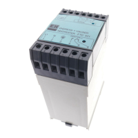
6.2 Alarm set point/fault monitoring
A relay with a changeover contact is allocated to each of the
two alarm set points SP1 and SP2. In the event of a set point
alarm condition or unit failure the relative relay is deactivated
(no power to coil). A front panel mounted yellow LED shows the
relay condition in accordance with the NE44 NAMUR standard:
LED “ON” on active relay (power to coil); LED “Off” on de-active
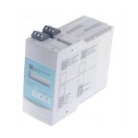
relay (no power to coil). The LC display indicates the form of
set point condition, exceeding or undercutting the preset value.
The following description is valid for the set
points
and
Parameter Variations
Default
settings
Actual
settings
* Operating mode
/
Setting the operating
mode for alarm set point
and fault monitoring
Minimum safety:
Event on undercutting the
switch threshold. In fault
condition
(I < 3.6 mA or > 21 mA) red
LED illuminates.
Maximum safety: Event on
exceeding the switch
threshold. In fault condition
(I < 3.6 mA or > 21 mA) red
LED illuminates.
:
:
* Switch thershold
/
Setting up the switch
threshold.
Value range:
00 to 99
:
:
* Hysteresis
/
Set up the hysteresis for
the switch threshold in
minimum/maximum
safety.
Value range:
/
Contactor
36
00 to 99
Equals a hysteresis of
1 to 100% ( + 1%)
 Loading...
