Installation
Hardware Installation and Maintenance Manual 3
–11
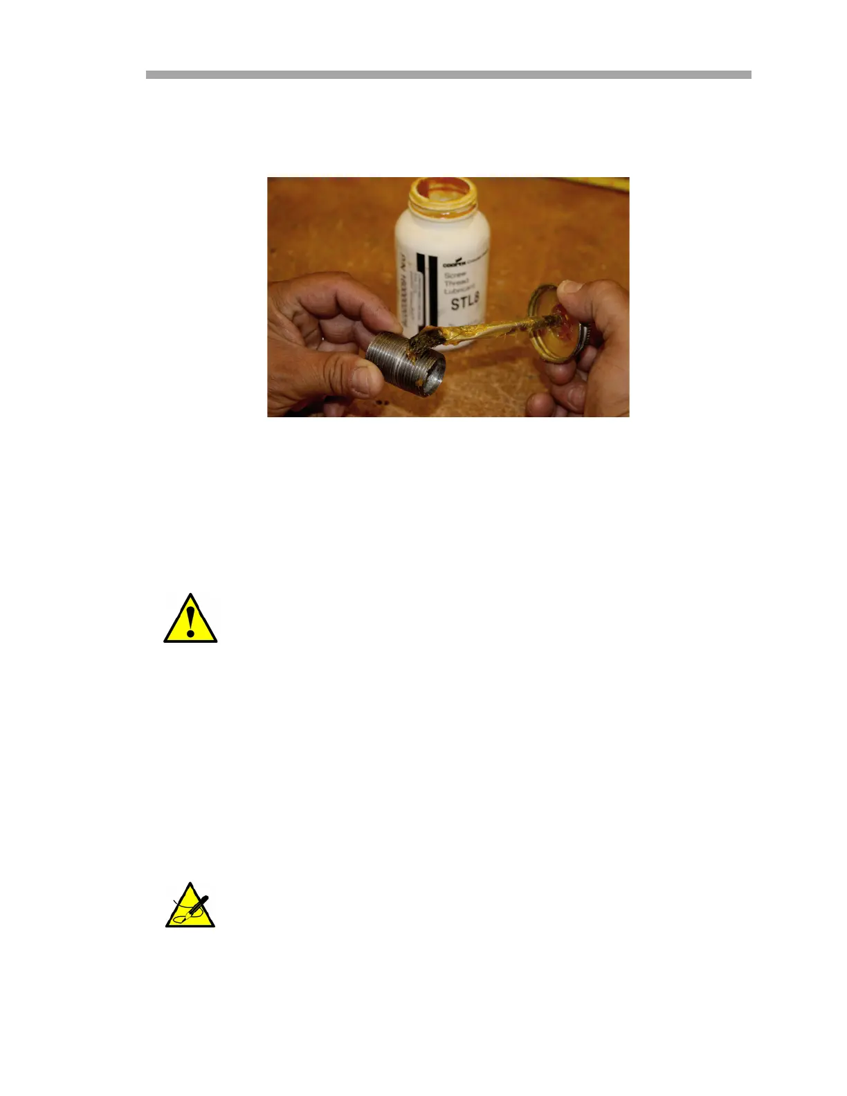
1. Holding the fitting piece at one end, generously apply the STL8
lubricant on the male threaded surface (at least five threads wide)
as shown in Figure 3–5 below.
2. Screw the female pipe thread onto the male fitting until the
lubricated threads are engaged.
Connecting the Output Signals and Alarms
The 4-20 mA current loop and serial output for each analyzer are supplied from
mating terminal blocks (TB2) located inside the respective analyzer electronics
enclosures, as shown in Figure 1–6 on page 1–11 and Figure 1–7 on page 1–12
(Analyzer A) or Figure 1–8 on page 1–13 and Figure 1–9 on page 1–14
(Analyzer B). By default, the 4-20 mA current loop outputs are factory set to
source current.
• Eyes: May cause minor irritation.
• Skin: May cause minor irritation.
• Ingestion: Relatively non-toxic. Ingestion may result in a
laxative effect. Ingestion of substantial quantities may cause
lithium toxicity.
The 4-20 mA current loop output is factory set to source current.
Refer to “Changing the 4-20 mA Current Loop Mode” on page
3-16 to change the 4-20 mA current loop output from source to
sink.
Figure 3–5 Applying conduit
lubricant

 Loading...