IQ7/IQ7+/IQ7X/IQ7A Microinverters Installation and Operation Manual
32 © 2023 Enphase Energy Inc. All rights reserved. September 2023
IOM-00028-1.0
5.2 Specifications
See the specifications in the following tables for:
• Enphase IQ7-60-2-US Microinverters
• Enphase IQ7PLUS-72-2-US Microinverters
• Enphase IQ7X-96-2-US Microinverters
• Enphase IQ7A-72-2-US Microinverters
• IQ Cable
5.2.1 IQ7-60-2-US Microinverter specifications
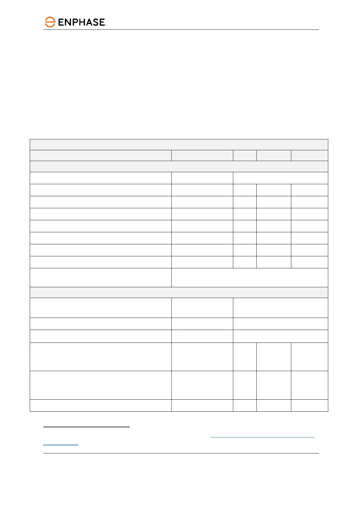
Enphase IQ7-60-2-US Microinverter parameters
Topic Unit Min Typical Max
DC Parameters
Commonly used module pairings
1
235 W – 350+ W
Peak power tracking voltage V 27 37
Operating voltage range V 16 48
Maximum input DC voltage V 48
Minimum/Maximum start voltage V 22 48
Maximum DC input short circuit current (module Isc) A 15
Overvoltage class DC port II
DC Port backfeed under single fault A 0
PV array configuration
1x1 ungrounded array; no additional DC side protection required;
AC side protection requires max 20 A per branch circuit
AC Parameters
Maximum continuous AC output power (-40°F to
+149°F)
VA 240
Peak output power VA 250
Power factor (adjustable)
0.85 leading …0.85 lagging
Nominal AC output voltage range
2
240 VAC (single phase)
208 VAC (single phase)
Vrms
Vrms
211
183
264
229
Nominal output current
240 VAC (single phase)
208 VAC (single phase)
Arms
Arms
1.0
1.15
Nominal frequency Hz 60
1
No enforced DC/AC ratio. See the compatibility calculator at enphase.com/en-us/support/module-
compatibility
2
Nominal Voltage Range can be extended if required by the utility.