IQ7/IQ7+/IQ7X/IQ7A Microinverters Installation and Operation Manual
39 © 2023 Enphase Energy Inc. All rights reserved. September 2023
IOM-00028-1.0
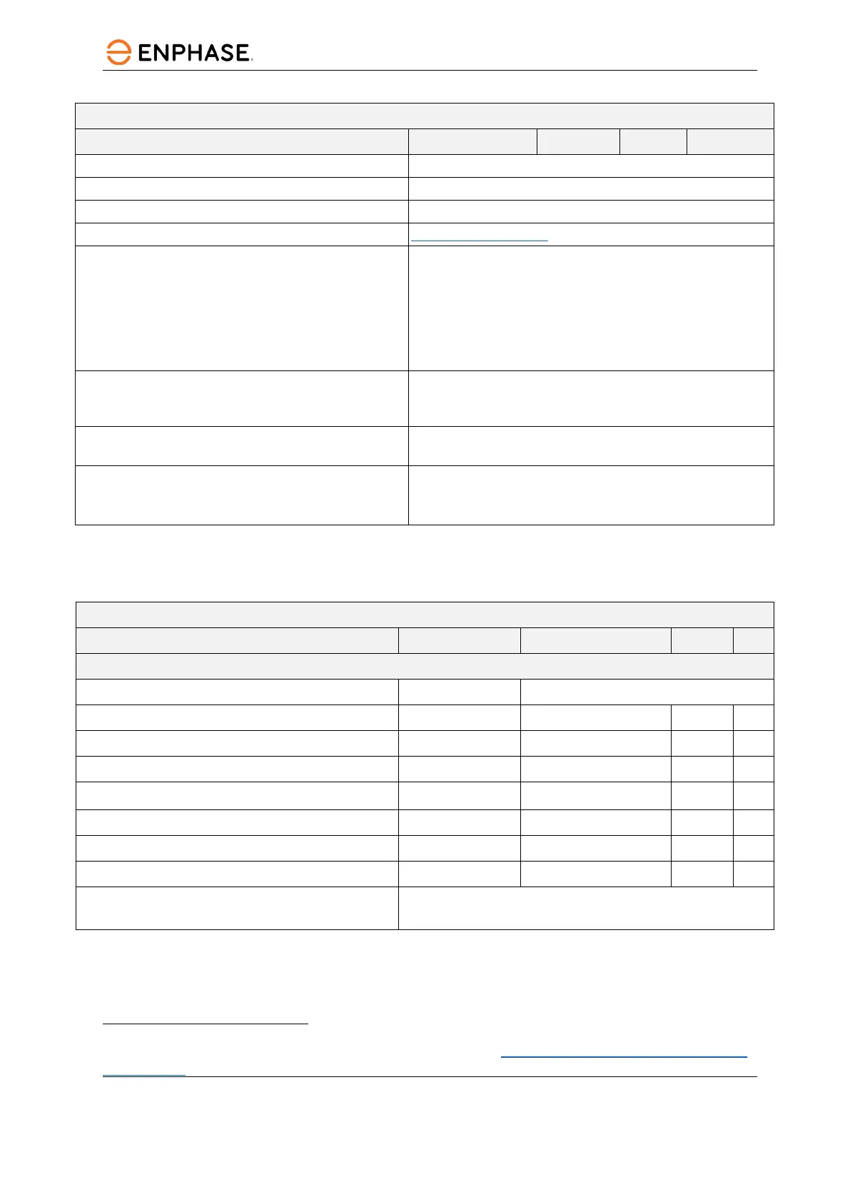
IQ7X-96-2-US Microinverter parameters
Topic Unit Min Typical Max
Approved for wet locations Yes
Pollution degree PD3
Communication Power line communication (PLC)
Standard warranty term enphase.com/warranty
Compliance
CA Rule 21 (UL 1741-SA) UL 62109-1, UL1741/IEEE1547, FCC Part 15
Class B, ICES-0003 Class B, CAN/CSA-C22.2 NO. 107.1-01
This product is UL Listed as PV Rapid Shut Down Equipment and
conforms with NEC-2014 and NEC-2017 section 690.12 and C22.1-
2015 Rule 64-218 Rapid Shutdown of PV Systems for the
conductors when installed according to manufacturer’s
instructions.
Grounding The DC circuit meets the requirements for ungrounded PV
arrays in NEC. Ground fault protection (GFP) is integrated into
the class II double-insulated microinverter.
Monitoring Enphase Installer Portal monitoring options require an Enphase
IQ Gateway.
Integrated DC disconnect/
Integrated AC disconnect
The DC and AC connectors have been evaluated and
approved for use as the load-break disconnect required by
NEC 690.
5.2.4 IQ7A-72-2-US Microinverter specifications
IQ7A-72-2-US Microinverter parameters
Topic Unit Min Typical Max
DC parameters
Commonly used module pairings
10
W 295 W – 460+ W
Peak power tracking voltage V 38 43
Operating range V 18 58
Maximum DC input voltage V 58
Minimum/Maximum start voltage V 30 58
Maximum DC input short circuit current (module Isc) A 15
Overvoltage class DC port II
DC Port backfeed under single fault A 0
PV array configuration
1x1 ungrounded array; no additional DC side protection required;
AC side protection requires max 20A per branch circuit
10
No enforced DC/AC ratio. See the compatibility calculator at enphase.com/en-us/support/module-
compatibility