M215 Installation and Operation
2013 Enphase Energy Inc. 141-00012 Rev 05
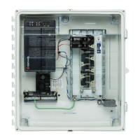
Step 2: Install the AC Branch Circuit Junction Box
DANGER: Risk of Electrical Shock. Be aware that installation of this equipment includes
risk of electric shock. Do not install the AC junction box without first removing AC power
from the Enphase System.
WARNING: Only use electrical system components approved for wet locations.
WARNING: Do NOT exceed the maximum number of microinverters in an AC branch
circuit as listed on page 27 of this manual. You must protect each microinverter AC
branch circuit with a 20 amp maximum breaker.
a. Size the AC wire gauge to account for voltage rise. Select the correct wire size based on the
distance from the beginning of the microinverter AC branch circuit to the breaker in the load
center.
All components of system wiring must be considered, including internal voltage rise within the
length of Engage Cable. Typically, three wire sections and several wire terminations must be
quantified. There is also some resistance associated with each circuit breaker. As all of these
resistances are in series, they add together. Since the same current is flowing through each
resistance, the total voltage rise is total current times the total resistance. For a single-phase
system, the total resistance is equal to two times the one-way resistance. For a three-phase
system, each of the three line currents and resistances must be calculated.
Standard guidelines for voltage rise on feeder and AC branch circuit conductors might not be
sufficient for microinverter AC branch circuits that contain the maximum allowable
microinverters. This is due to high inherent voltage rise on the AC branch circuit.
For more information, refer to our Technical Brief, Voltage Drop Considerations for M215.
b. Install an appropriate junction box at a suitable location on the PV racking system. You can
center feed the branch, or you can install the junction box at the end of a row of PV modules.
Best Practice: Center-feed the branch circuit to minimize voltage rise in a fully populated
branch. This practice greatly reduces the voltage rise as compared with an end-fed
branch. To center-feed a branch, divide the circuit into two sub-branch circuits protected
by a single overcurrent protection device (OCPD).
c. Provide an AC connection from the AC junction box back to
the electrical utility connection using equipment and practices
as required by the NEC and local jurisdictions.
 Loading...


