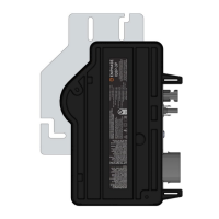
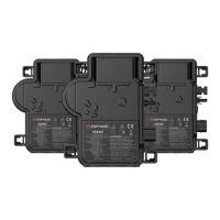
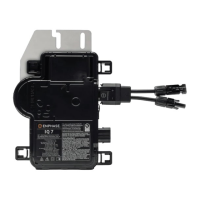
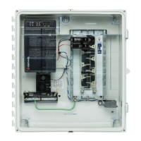
M215 Installation and Operation
2013 Enphase Energy Inc. 141-00012 Rev 05
Table of Contents
Important Safety Information ......................................................................................................................... 4
Read this First .................................................................................................................................................. 4
Safety Instructions ........................................................................................................................................... 4
The Enphase Microinverter System .............................................................................................................. 5
How the Microinverter Works ........................................................................................................................... 6
System Monitoring ....................................................................................................................................... 6
Optimal Reliability ........................................................................................................................................ 6
Ease of Design ............................................................................................................................................ 6
Planning for Microinverter Installation ........................................................................................................... 7
Compatibility and Capacity .............................................................................................................................. 7
Electrical Compatibility ................................................................................................................................ 7
Branch Circuit Capacity ............................................................................................................................... 7
Parts and Tools Required ................................................................................................................................ 8
Enphase Equipment .................................................................................................................................... 8
Other Items .................................................................................................................................................. 8
Lightning and Surge Suppression .................................................................................................................... 8
Enphase Microinverter Installation ................................................................................................................ 9
Step 1: Measure AC Voltage at the Electrical Utility Connection ................................................................... 10
Step 2: Install the AC Branch Circuit Junction Box ........................................................................................ 11
Step 3: Position the Enphase Engage Cable ................................................................................................. 12
Step 4: Attach the Microinverters to the PV Racking ..................................................................................... 13
Step 5: Ground the System ............................................................................................................................ 14
Step 6: Dress the Engage Cable ................................................................................................................... 15
Step 7: Connect the Microinverters ................................................................................................................ 16
Step 8: Terminate the Unused End of the Engage Cable .............................................................................. 17
Step 9: Connect the Engage Cable to AC Junction Box(es) .......................................................................... 18
Step 10: Complete the Installation Map ......................................................................................................... 19
Step 11: Connect the PV Modules ................................................................................................................. 19
Commissioning and Operation .................................................................................................................... 20
Energize the System ...................................................................................................................................... 20
Build the Virtual Array .................................................................................................................................... 20
M215 Operation ............................................................................................................................................. 20
Troubleshooting .......................................................................................................................................... 21
Status LED Indications and Error Reporting .................................................................................................. 21
Startup LED Operation: ............................................................................................................................. 21
Post-Startup LED Indications..................................................................................................................... 21
GFDI Fault ................................................................................................................................................. 21
Other Faults ............................................................................................................................................... 21
Troubleshoot an Inoperable Microinverter ..................................................................................................... 22
Disconnect a Microinverter from the PV Module ............................................................................................ 24
Install a Replacement Microinverter ............................................................................................................... 25
Technical Data ............................................................................................................................................ 26
Technical Considerations ............................................................................................................................... 26
M215 Specifications ....................................................................................................................................... 26
Engage Cable Specifications ......................................................................................................................... 28
Engage Cable Planning and Ordering Information ........................................................................................ 29
Selecting Cable Type ................................................................................................................................ 29
Connector Spacing Options ....................................................................................................................... 29
Voltage Types and Conductor Count ......................................................................................................... 30
Racking Compatibility ................................................................................................................................ 30
Cabling Length Options ............................................................................................................................. 30
Planning for Cable Lengths and Type ....................................................................................................... 30
Enphase Installation Map ............................................................................................................................... 32
M215 Dimensions .......................................................................................................................................... 33
Sample Wiring Diagram: M215, 240 VAC ...................................................................................................... 34
Sample Wiring Diagram: M215, 208 VAC ...................................................................................................... 35
 Loading...


