EasyManuals Logo

Enterasys Matrix N7 7C107 User Manual

Enterasys Matrix N7 7C107
52 pages
To Next Page IconTo Next Page
To Previous Page IconTo Previous Page
Page #43 background imageLoading...
Page #43 background image
Setting Up the Enterasys Matrix N7 Chassis
Enterasys Matrix N7 Chassis Setup 3-15
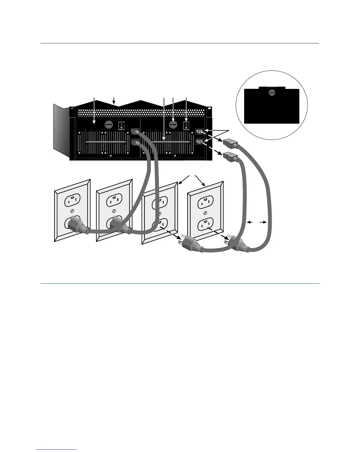
Figure 3-8 Removing a Power Supply from a Powered-Up Chassis
1 Power switch 4 AC power connector 7 N7 chassis
2 AC power cord 5 Power supply 8 Power supply handle
3 15A/120 Vac power outlet 6 Captive slotted-head screw 9 Example of blank plate
50/60Hz
LINE 2:
100-125V~12A
200-240V~6A
50/60Hz
LINE 1:
100-125V~10A
200-240V~5A
POWER FAN
PS1
50/60Hz
LINE 2:
100-125V~12A
200-240V~6A
50/60Hz
LINE 1:
100-125V~10A
200-240V~5A
POWER FAN
PS2
Ç
Á
Â
Ã
ÄÆ À
Å
È

Table of Contents

Other manuals for Enterasys Matrix N7 7C107

Questions and Answers:

Question and Answer IconNeed help?

Do you have a question about the Enterasys Matrix N7 7C107 and is the answer not in the manual?

Enterasys Matrix N7 7C107 Specifications

General IconGeneral
BrandEnterasys
ModelMatrix N7 7C107
CategoryChassis
LanguageEnglish

Related product manuals